“Under the hood” of SOLIDWORKS Flow Simulation
The field of Computation Fluid Dynamics (CFD) is a sophisticated engineering discipline based on the Reynolds Averaged Navier-Stokes (RANS) equations that govern fluid flow, heat and mass transfer. CFD has a reputation for being extremely complicated and has typically been the domain of specialists, physicists and academics, using super computers.
Typically, the quality of CFD results is greatly affected by the quality of the mesh and the attentiveness of the user to the pre-processing stage. Consequently, traditional CFD software codes are very difficult to use. The user must first master the complicated pre-processing methods and also possess a deep understanding of the underlying physics and mathematics.
Fortunately, the developers of SOLDWORKS Flow Simulation, had a different philosophy in mind. They focused on the needs of design engineers utilizing off-the-shelf engineering PC workstations. They sought to create software that prioritized speed, accuracy and ease-of-use, instead of requiring the user to adapt to the limitation or complexities of the software.
SOLIDWORKS Flow Simulation has achieved this breakthrough in CFD by utilizing technology called SmartCells. In this two-part blog I will peek “under the hood” of SOLIDWORKS Flow Simulation to explain what makes SmartCell technology so powerful.
What are SmartCells? Below is a list of the underlying characteristics of SmartCells.
- SmartCells are Cartesian based meshes that are typically an order of magnitude smaller in size than traditional CFD meshes while still providing the same level of resolution and accuracy
- SmartCells handle complex geometries which may have many interfaces between fluid and solid all within one mesh cell
- SmartCells have embedded intelligence which is used to speed up the solution process
- SmartCells can handle turbulent boundary layers accurately in all fluid flow processes
- SmartCells combine easier pre-processing, smaller meshes and faster run times, resulting in significant increases in productivity and throughput, bringing the practical application of CFD well within the capabilities of design engineers
I will expand and explain each characteristic in more detail to follow.
SmartCells are Cartesian based meshes that are typically an order of magnitude smaller in size than traditional CFD meshes while still providing the same level of resolution and accuracy
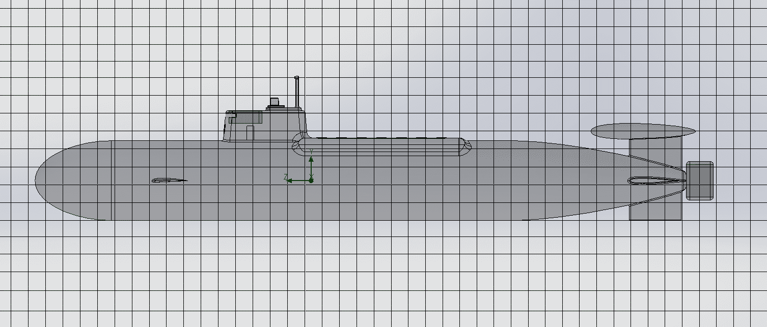
Traditional CFD tools are typically based on body-fitted algorithms. In other words, in order to obtain a mesh of the fluid volume, first the user must mesh the surfaces of the body and then grow those surface meshes outwards into a three-dimensional volume mesh. SmartCells use an alternative approach called an immersed-body mesh. In this approach, the mesh is created independently from the geometry itself and the mesh cells can intersect the bodies in an arbitrary fashion.
The immersed-body mesh is simply a set of cuboids (rectangular cells) orientated along the global Cartesian coordinate system. These cuboids form the basic “global” mesh that is the starting point of any SOLIDWORKS Flow Simulation project. Cuboids that are intersected by body surfaces are treated in a special way, described later in the blog, according to the boundary conditions defined on the surface.
 Figure 1: Immersed body mesh of a submarine body
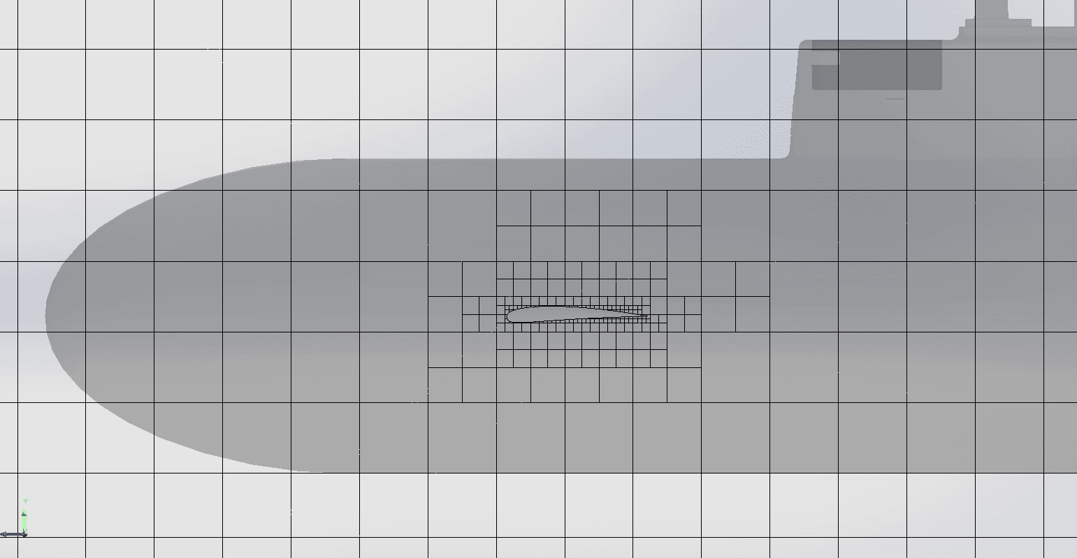
Cuboids can be subdivided into smaller cuboids for better resolution of more intricate geometry or high flow gradients.
 Figure 2: Mesh subdivision around forward hydroplane on submarine
Cartesian grids are ideal because they are inherently the most accurate cell type. They do not suffer from reduced cell accuracy as a result of skewness or large aspect ratios that typically occur in body fitted meshes when cells are adapting to the geometry.
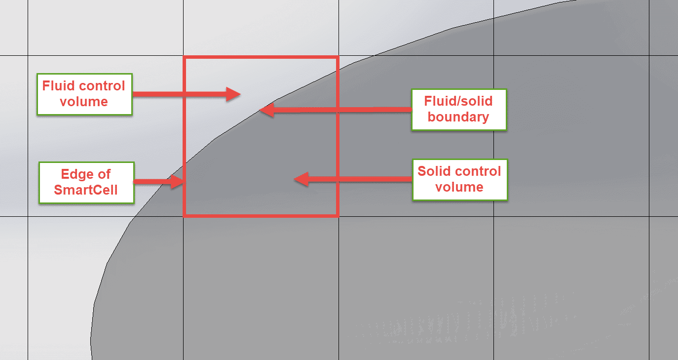
As a result of using Cartesian-based grids, there are always cells which are located fully in a solid body (solid cells), fully in a fluid zone (fluid cells), and finally cells which intersect the boundary between fluid and solid. In the simplest case, a Cartesian cell on the fluid/solid boundary consists of 2 control volumes (CV); a fluid CV and a solid CV.
 Figure 3: Simple SmartCell near nose of submarine with 2 control volumes (CV)
Because SOLIDWORKS Flow Simulation is completely embedded inside the SOLIDWORKS 3D CAD environment, all of the necessary geometric parameters of each control volume can be calculated by extracting the data directly from the native SOLIDWORKS 3D CAD model.
SmartCells handle complex geometries which may have many interfaces between fluid and solid all within one mesh cell
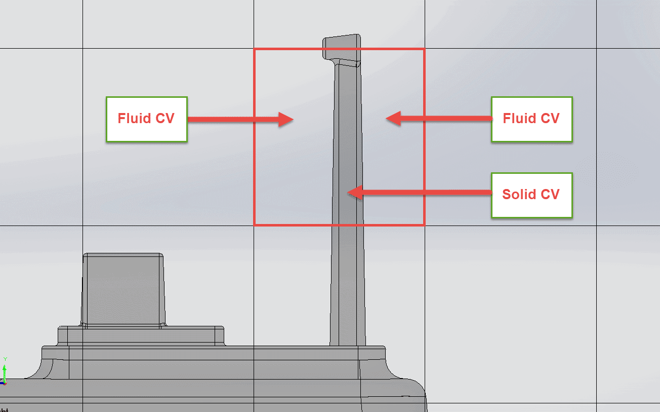
SmartCell technology is not limited to the simple case of just one fluid CV and one solid CV. In fact, within one single cell it is possible to have an arbitrary number of control volumes: 3 in the case of a thin walled body (fluid CV – solid CV – fluid CV) or more in the case of several layers of materials with different properties inside of a thin-walled body. The code can handle as many as 20 CVs inside one SmartCell!
Because of the ever-present link between SOLIDWORKS Flow Simulation and the SOLIDWORKS 3D CAD model, SmartCells provide good resolution of geometric features even in the case of relatively coarse meshes. The solid and fluid control volumes can be alternated many times within each SmartCell.
 Figure 4: Multiple CV’s within a single SmartCell
I hope this blog has piqued your interest in SmartCells, the innovative technology that makes SOLIDWORKS Flow Simulation the powerful, yet extremely easy-to-use CFD package that it is. In part 2 of the blog I will expand on the other key advantages that SmartCells offer. If you just can’t wait until then, feel free to read this whitepaper explaining SmartCell technology in more detail.
In the meantime go design some innovative products with the help SOLIDWORKS Flow Simulation.
Alon Finkelstein
Simulation Product Specialist
Computer Aided Technology, Inc.

 Blog
Blog