SOLIDWORKS Tools: Check Sketch for Feature and Repair Sketch
There are 2 tools within SOLIDWORKS that help users identify sketch errors and fix them too. They are Check Sketch for Feature and Repair Sketch.
Check Sketch for Feature is a tool that checks a sketch used for a feature creation. Sketches are checked according to the contour type required by the feature type (i.e. Extruded Boss/Base or Extruded Cut). If the sketch passes the checks, a NO PROBLEM FOUND message will be displayed. If there is an error, a message will describe the error and highlight the error, if appropriate.
Let’s explore this tool…
Here is a sketch drawn on face of a part. The sketch is fully defined and there are no apparent errors in the sketch according to the feature tree but, as you can see, the Cut-Extrude1 cannot be created.
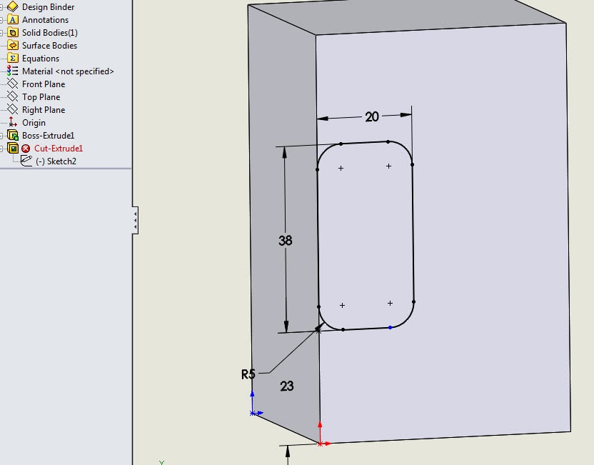
By right-mouse clicking on the Cut feature, we access What’s Wrong. Click the What’s Wrong and the dialog box displays this message:

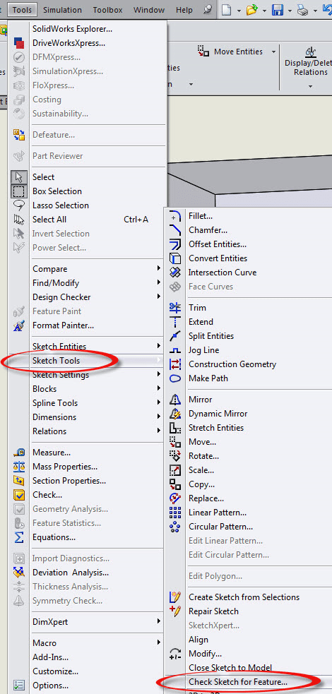
Close the What’s Wrong window and go to Tools > Sketch Tools > Check Sketch for Feature.
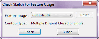
The Check Sketch for Feature Usage window appears. In this case, the Feature Usage is the Cut Extrude. There is a Contour Type which states that there are Multiple Disjoint Closed or Single.
Click Check. Although the bix states no problems, the check does state that the sketch contains 1 open contour. Be aware of the messages and read entirely.
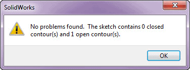
Click OK and go to Tools > Sketch Tools > Repair Sketch.
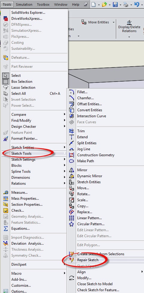
A Repair Sketch dialog appears and shows the error (s). In this case, there is 1 very small gap in the sketch geometry. The Magnify Glass defines where the error is.
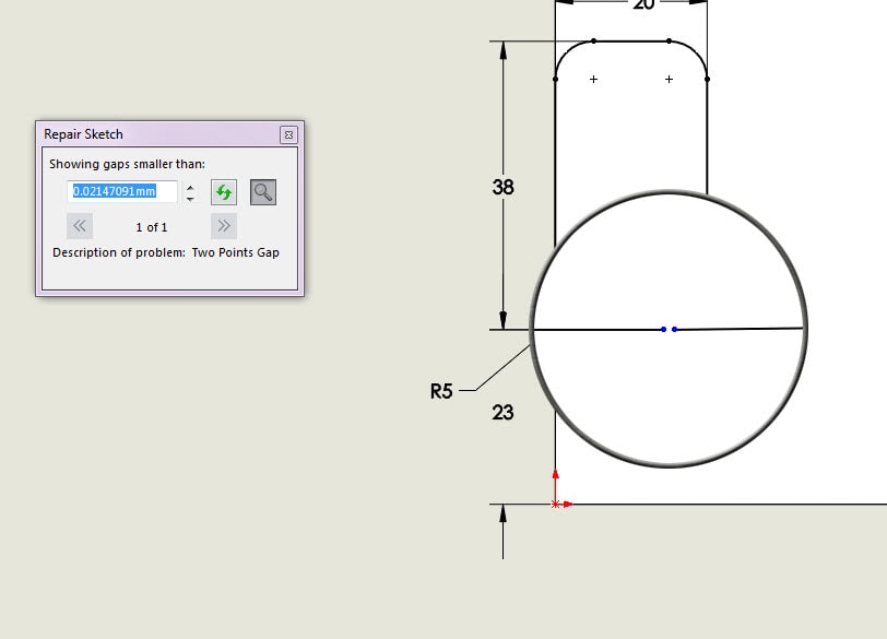
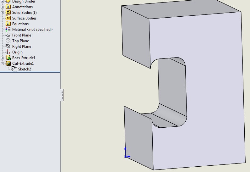
“X” out of the Repair Sketch window and repair the sketch. When finished, exit the sketch and the part will rebuild with no errors.
Thank you for visiting our CATI blog!
Judy Marlo
CATI Application Engineer

 Blog
Blog