Surface Splines and Equation Splines
Surface Splines and Equation Splines
Making interesting geometry in regards to potential cam and slider surfaces is made much easier by use of the 3D sketching abilities and surface splines. For a brief example, we will be creating a barrel cam and the appropriate cam groove in the part.
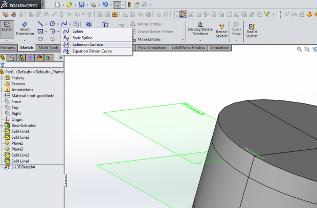
To start, I used a simple cylinder of radius 50mm and thickness of 50mm. Once I had a cylinder, I used reference planes and default planes to create the split lines shown:
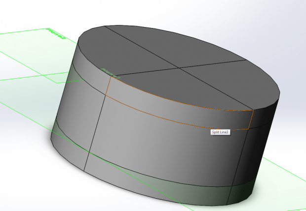
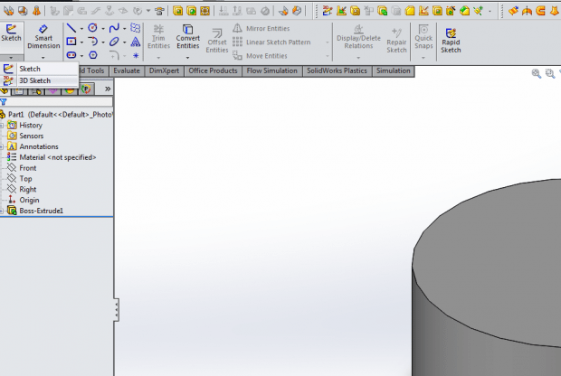
Once I had my cylinder setup with the geometry pattern pre-sketched, I moved on to the actual sketch.
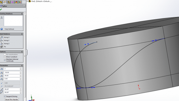
Once you have that open, it is time to start our sketch. Using the spline on surface tool, draw the basic profile for the barrel cam recess:
Then, using the top of the cylinder as the sketch plane, draw a semi-circle of the same radius as the cylinder above the sketched spline.
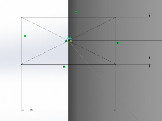
After this, I drew a square on the front plane, with the following relations shown to the spline:
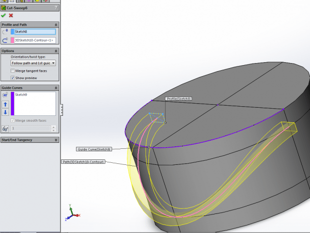
From there, we are ready to do the fun part and actually sweep the cut. Notice the settings used and the use of one of the sketches as a guide curve. This is why it is important to make 2 sketches as the swept cut tool does not allow the path and the guide curve to come from the same sketch.
With everything selected, it should look similar to this:
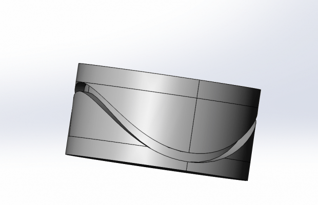
Once you have the half cut, you can mirror the feature to get a full encirclement of the cam profile. One is probably tempted to ask why the spline was not drawn all the way around the cylinder to avoid the mirror step. However, the program will not properly evaluate a closed loop for a swept cut as it results in zero-thickness geometry. As such, building it as a half and mirroring it is the proper way.
With everything made and mirrored, one should be left with the following:
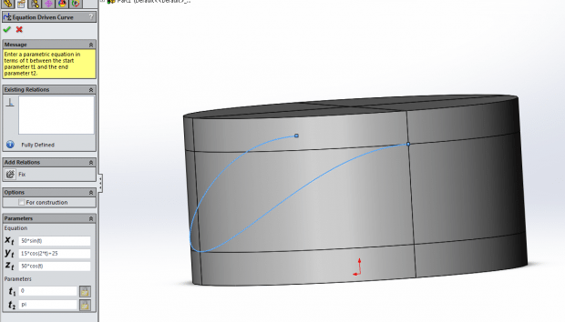
It is worth noting that this feature can also be made by defining a spline by a set of 3D parametric equations that would also work. In this case, one could generate two curves and sweep the profile.
The equation driven spline works slightly differently, using the equation to render the spline in 3D space. For these parameters, the Xt and Zt define the circle with the coefficient equal to the radius of the spline circle. The Yt parameter defines both the vertical position of the curve and the amplitude of the wave. It is also important to note that the t parameter goes only from 0 to pi, and not a full circle. This is once again the closed contour problem mentioned earlier:
I hope these tips help you make more successful at sweeping cuts while reducing the fear of the complicated sweep cut options.
Post By: Drew Potter

 Blog
Blog 