SOLIDWORKS Surfacing Trick for Mold Design
I discovered a cool feature last week while working on a customer’s mold design part that I think is worth making everyone aware of.
One of the main goals/achievements when making a mold for a part is always trying to get the “parting surface or runoff surface” exactly how you want it. Sometimes this means coming off at an exact angle at an exact location all the way around a rounded edge. How can we do that in SOLIDWORKS?
On the SOLIDWORKS CURVES toolbar is a command called SPLIT LINE.

You may have used this before to project sketches onto a face to “split up” the face into multiple faces for various reasons (being more exact with a load location in a Simulation analysis, creating edges to use as hold lines in filleting, or many other things). There are two other options in the SPLIT LINE command though that are pretty cool for mold design and surfacing in general. The one we are going to look at today is the SILHOUETTE option.
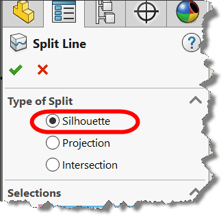
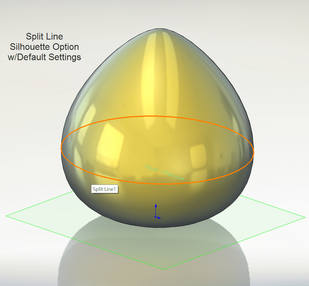
This option will generate a split line (hard edge and division of faces) where a selected PLANE projects through the model’s outer edges (i.e. the “extreme” silhouette edge like if you shined a light on it).
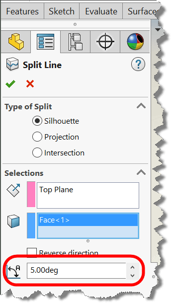
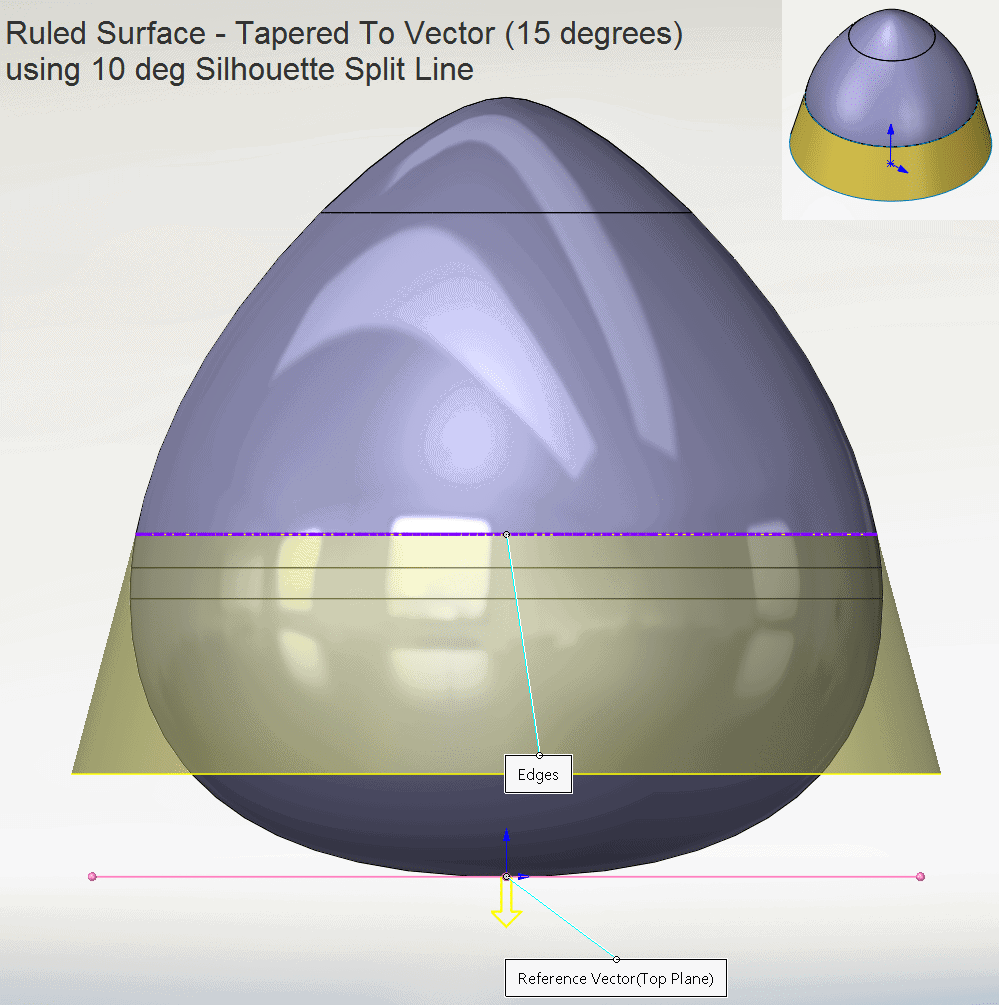
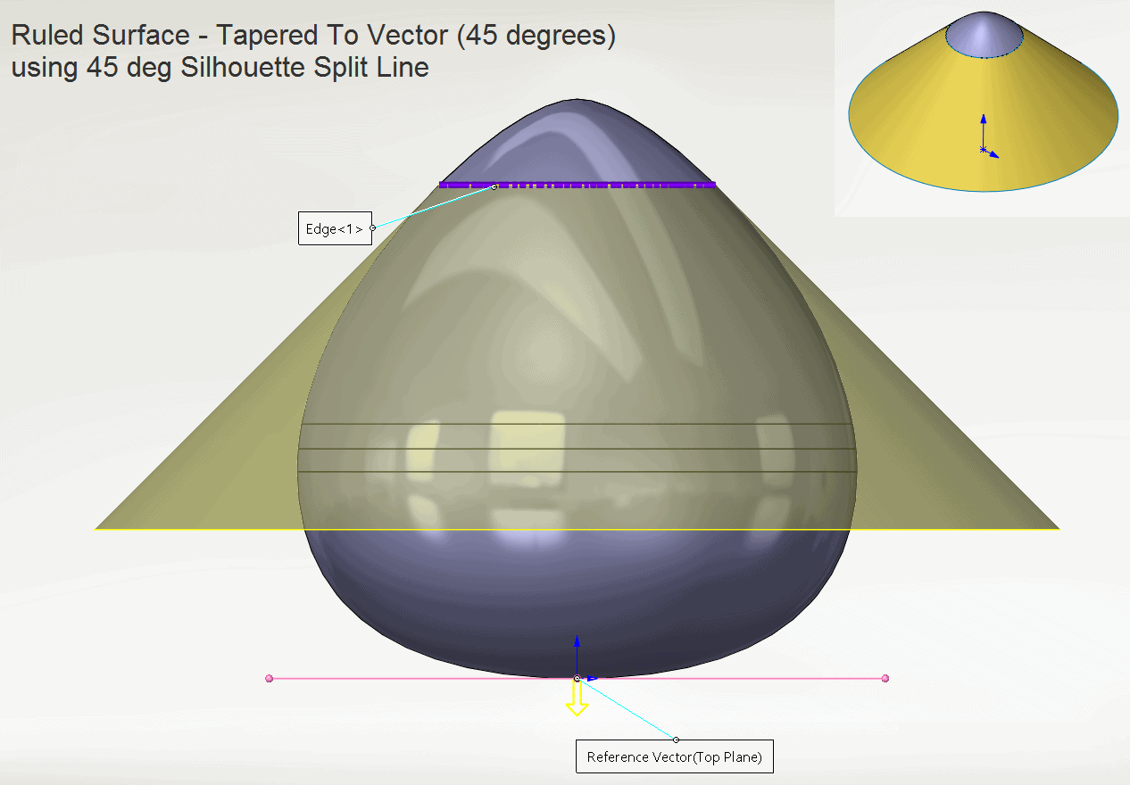
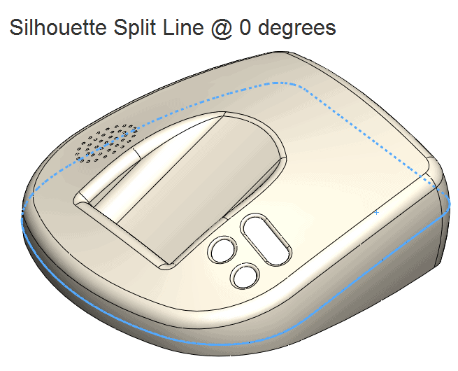
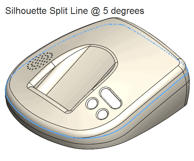
The discovery I made in this command was that you don’t have to accept the “extreme” silhouette edges as the result! There is an option at the very bottom that will let you adjust the ANGLE that it is going to hit the faces you are splitting. The default is at 0 degrees (the extreme edges). You can see here what happens if you adjust the angle.
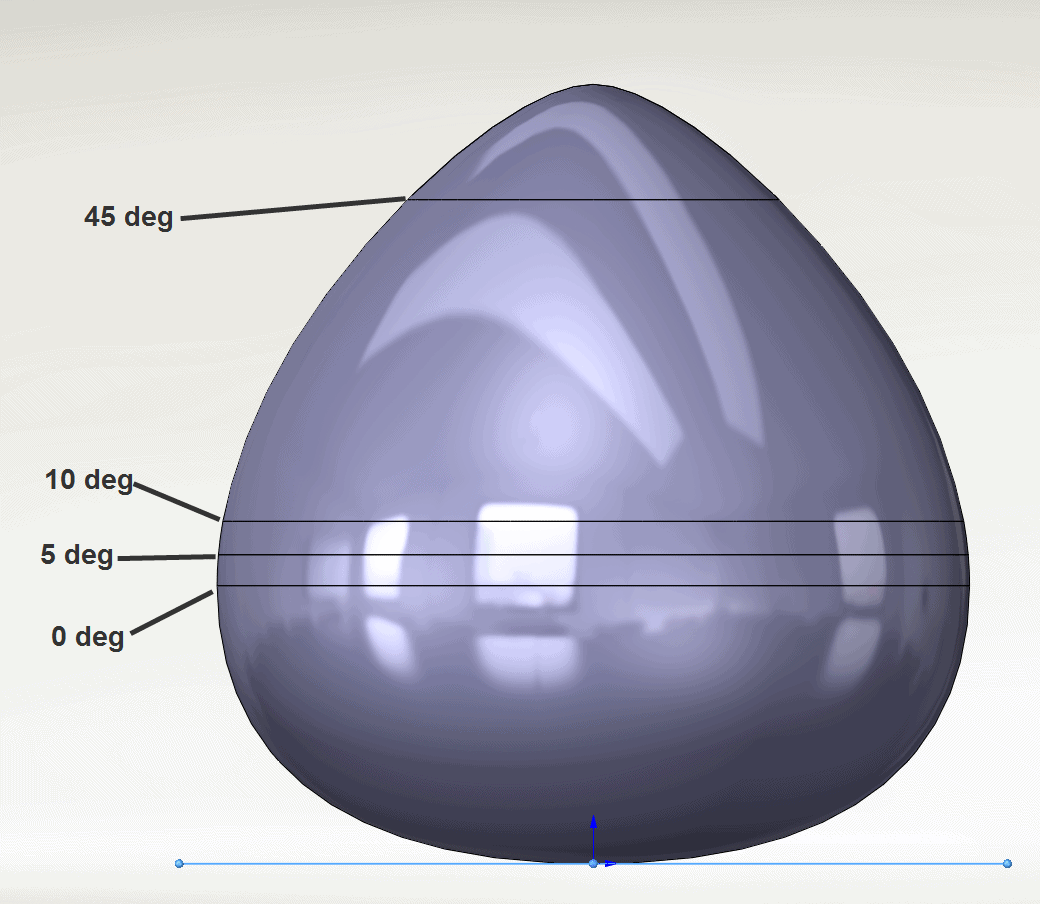
This allows you to get the split line EXACTLY where you want it on a part. Super cool!!
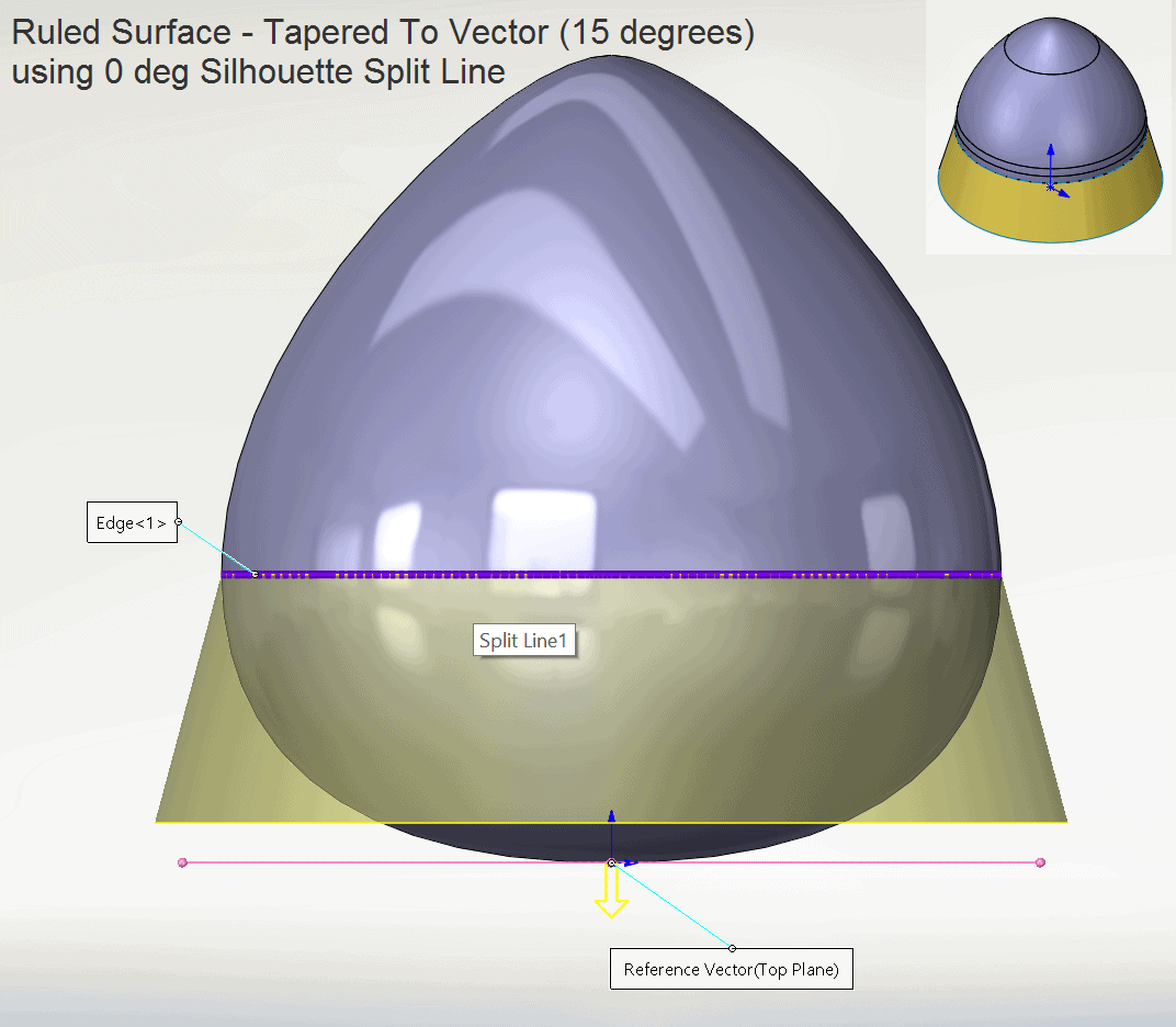
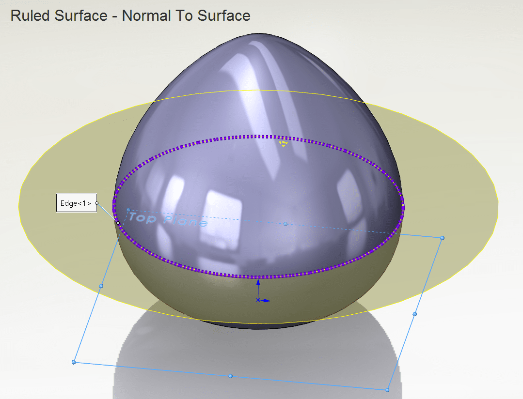
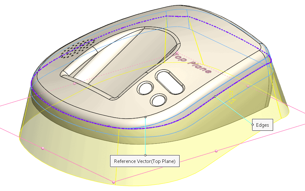
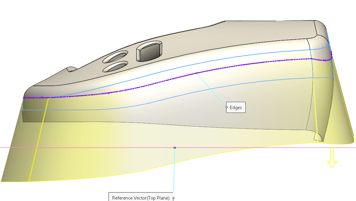
Then of course you can use that SPLIT LINE to generate a RULED SURFACE or RADIATED SURFACE for your parting surface/runoff surface. Here are some comparisons/results that you may have never known you could do just by adjusting the Silhouette Split Line angle…
This works great on more complex parts just the same!
Try it out on your next surfacing challenge and see if it gives you the precision you desire!

 Blog
Blog