SOLIDWORKS Smart Drawing Blocks – Using Attributes as Editable Text Fields
Using Blocks in your SOLIDWORKS Drawings is a great way to re-use symbols and other sketch collections, so you don’t have to constantly draw them over and over. But what if you need those re-usable blocks to contain customizable information?
Customize Blocks
An often-overlooked capability of blocks is the ability to include editable Attributes.
This allows you to designate any Notes in the block as a unique Attribute with its own Name and Value.
You can then edit this Attribute on the fly by double-clicking it or even link it to your Custom Properties to have it update automatically.
In this scenario, we are creating our own custom flag which will call out a Material Code and Thickness of Material. We will also be linking this information to the Model Custom Properties so we can re-use this symbol on different drawings.
Start by sketching your custom symbol on a blank sheet and adding an Annotation Note where we want our custom Material information to go.

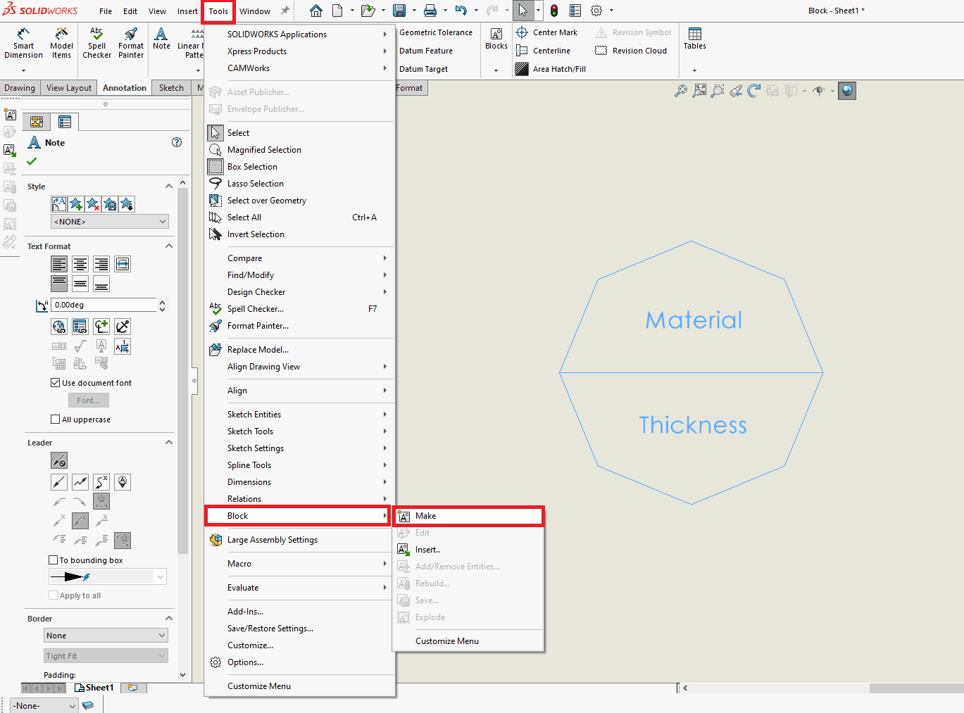
To make our symbol a block, highlight everything and go to Tools > Block > Make.
You can optionally designate an Insertion Point and Leader Point by expanding the Insertion Point section.
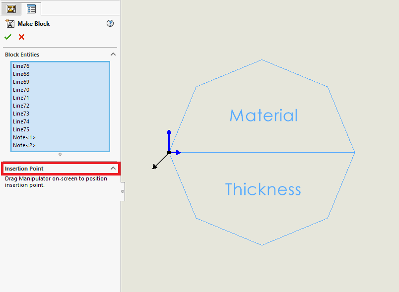
Tech Tip: You can drag the blue and black locators separately with the blue indicator specifying your Insertion Point and the black indicator specifying the Leader origin.
Once the Block is created, select the Block and you should see the Attributes button greyed out.
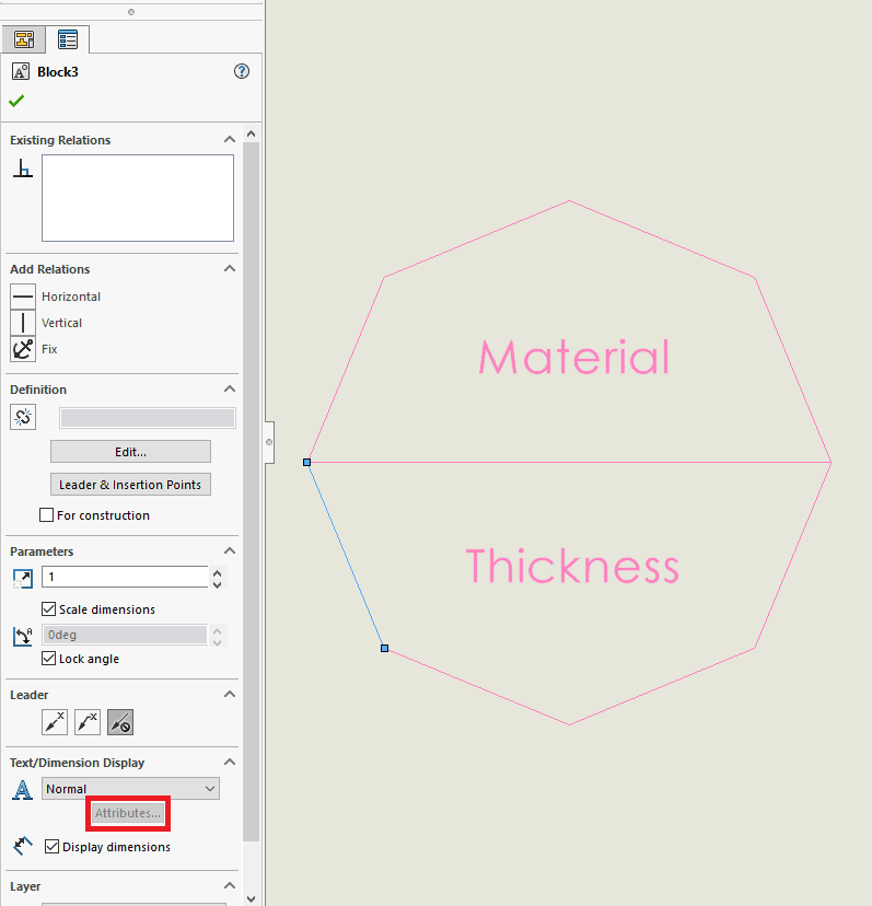
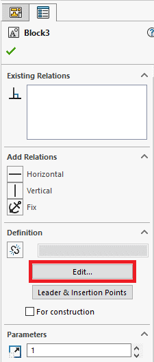
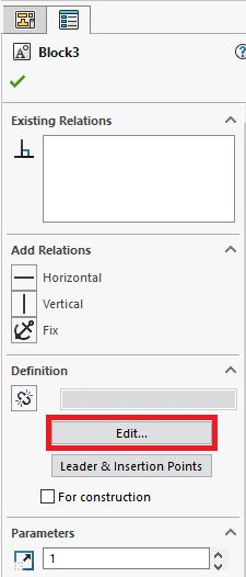
To add our Notes as Attributes, select the Edit button after selecting the Block.
Now that we are editing the Block, select a Note and you should have the ability to give it an Attribute Name. We will name the Attributes, Material and Thickness.
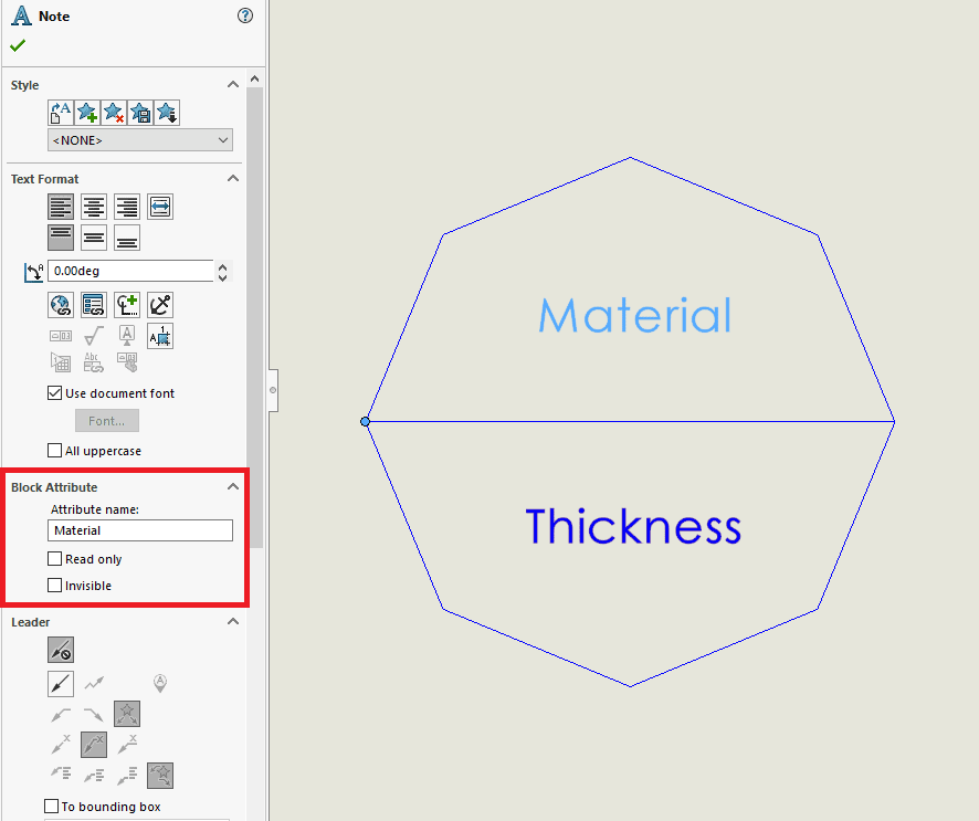
Tech Tip: You can set each Attribute as Read only or Invisible. Read only makes it so a user cannot change an Attribute value and Invisible makes it invisible to the user.
Once we’ve named our Attributes, exit Edit Block mode and save your changes by selecting the Exit and Save Changes icon in the top right.
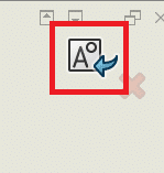
Now when we select our Block, we should see the Attributes button, no longer greyed out. Selecting this shows us a list of the Attributes contained in the Block.
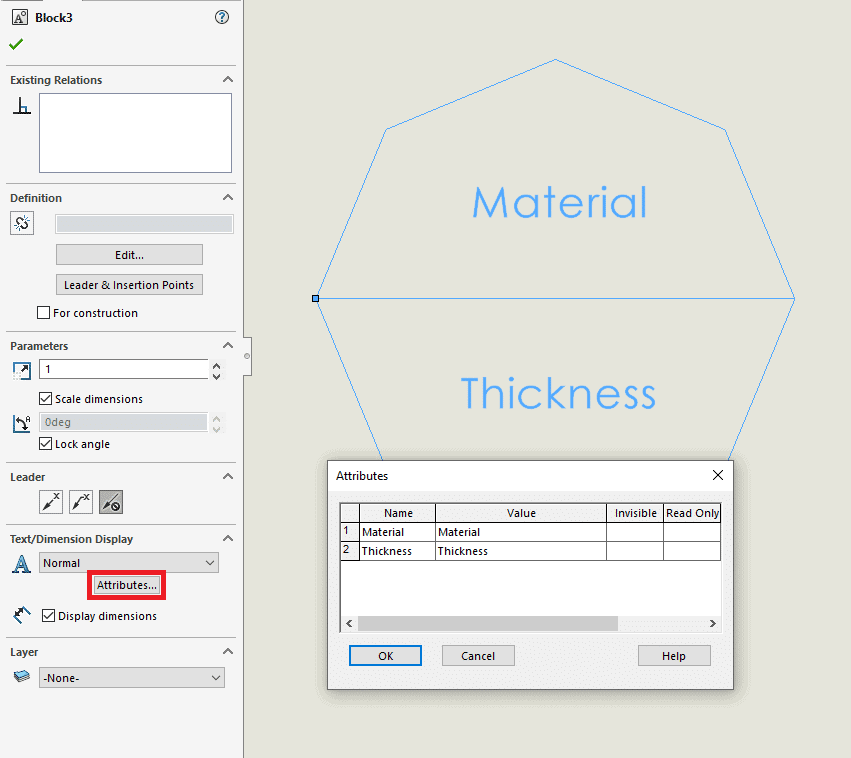
You can now change the Value of the Attribute by typing it here or even by double-clicking the Attribute at any time and typing a new Value.
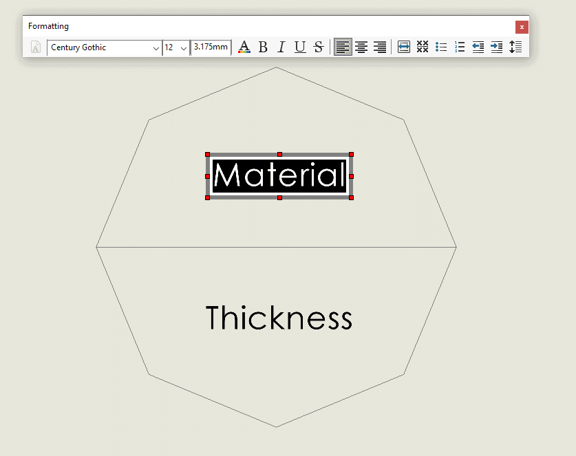
We now have user editable fields in our Blocks to allow us to change these values on the fly and can re-use these blocks in any other drawings. But what if we want those values to now link to Custom Property values?
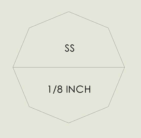
Let’s start by making sure we have the appropriate Custom Properties setup in our Part Model. With your Part Model open, go to File > Properties and create two Custom Properties for MaterialCode and MaterialThickness, which we’ll set to “SS” and “1/8 INCH”.

Now to link our Attributes to our new Custom Properties.
Tech Tip: For this to work, you will need to insert at least one Model View of our Part Model with the Custom Properties we want to link to.
Select your Block and select Edit to change the Note value in the Block.
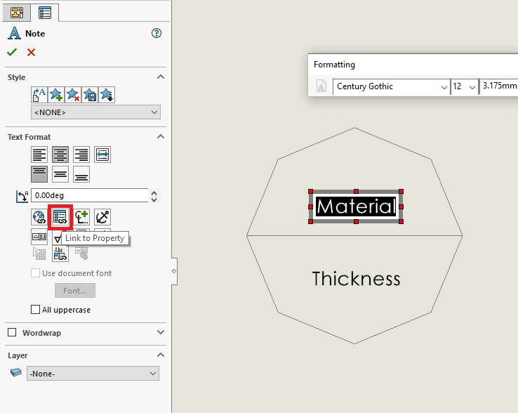
Now edit your Note by double-clicking it and while editing the Note, select the Link to Property button in the Property Manager.
In the Link to Property dialog, you should be able to select Model found here and under Property name: in the drop-down, select the Custom Property you want to link it to. In this case, we’ll select MatieralCode.
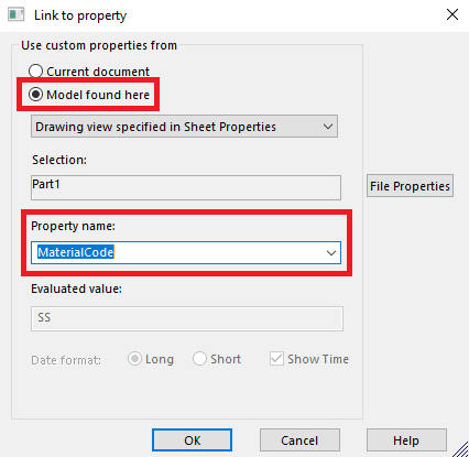
Tech Tip: You can also link to the Custom Properties in the Drawing file by selecting Current Document.
Once you hit OK on the Link to Property dialog, you should see the linked pointer to the Custom Property in the Model as: $PRPSHEET:“MaterialCode”
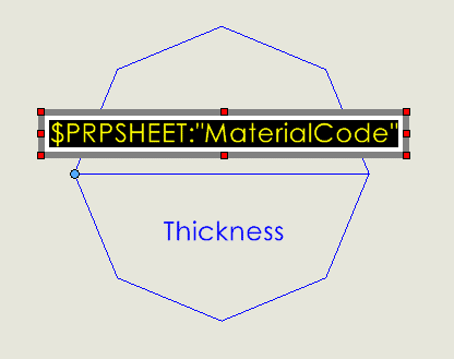
Tech Tip: If you know the correct syntax, you can also just type the Custom Property pointer directly into the Attributes box when selecting your Block.
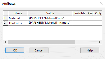
And there you have it. Now your Block will automatically look for Model Custom Properties on whichever Drawing you decide to use it on.
Jordan Puentes
Sr. Application Engineer
Computer Aided Technology, Inc.

 Blog
Blog