SOLIDWORKS: Hole Pattern Spacing With Equations
One of the first things you learn in SOLIDWORKS, is how to use the Smart Dimension tool to fully define your sketches. The Smart Dimension tool is very intuitive. You simply select the items you want to dimension and, depending on where you place the resulting dimension, SOLIDWORKS creates the parameter. There are a several other dimension tools for applying dimensions to our sketches. We have options for Chain, Baseline, Ordinate, and even a few more. For this post we are going to take advantage of the Path Length Dimension option.
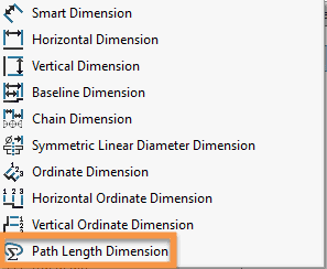
More specifically, we are going to use this Path Length Dimension as a reference dimension in an equation.
Here is the design request that we received. Pretty impressive graphics design work!
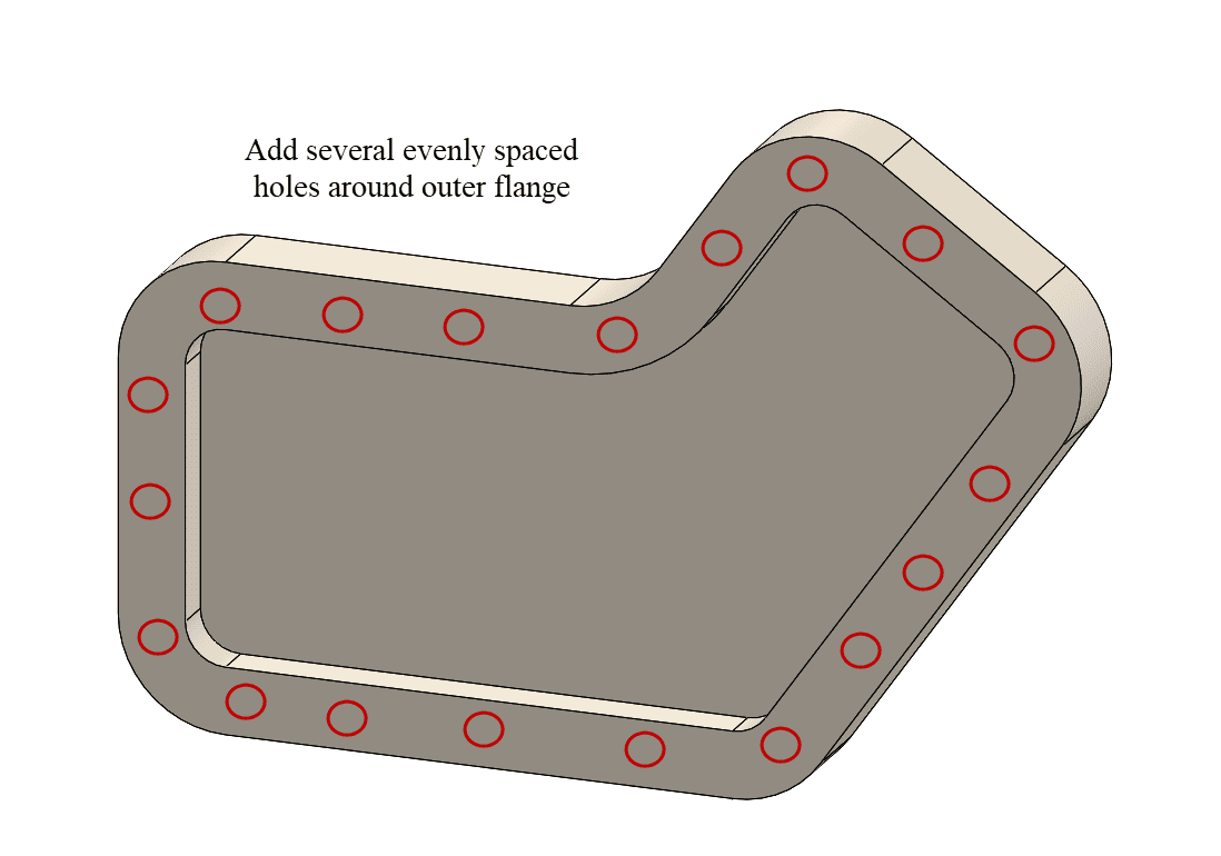
To accomplish this task, we will utilize the Hole Wizard feature and create a Curve Driven Pattern to get our complete array of holes. That sounds easy enough; but what if the part geometry changes? Will we need to edit the pattern to add more holes?
To fully capture this design intent, we want the quantity of these equally spaced holes to be driven by our part size. We will accomplish this by using an equation to define the quantity of holes, relating it to a Path Length Dimension value.
Let’s look deeper into the steps to accomplish this task.
Creating a sketch on the flange of the part, and using the Offset Entities command, gives us the curve to drive our pattern. Using this Path Length Dimension tool is simple. Selecting all these sketch segments and it quickly creates the driven dimension that is the entire length of those segments.
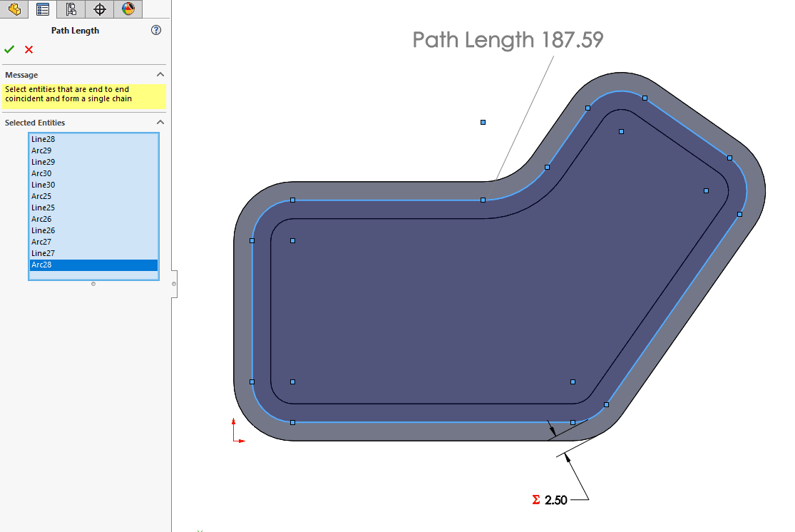
Going into the equation editor makes it easy to create Global Variables. We are going to create a new global variable named “Path_Length” and link it the Path Length reference dimension we just created. Linking a Global Variable to this dimension will make it easier for us to use it in our equation.
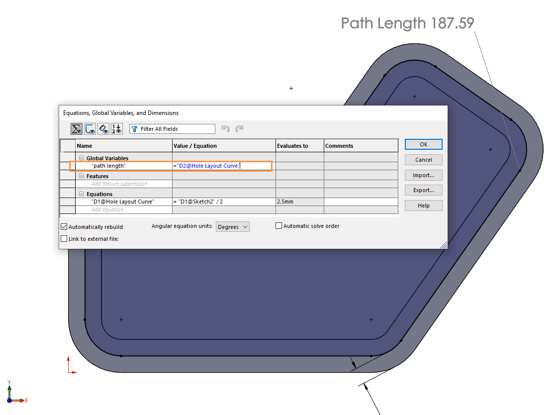
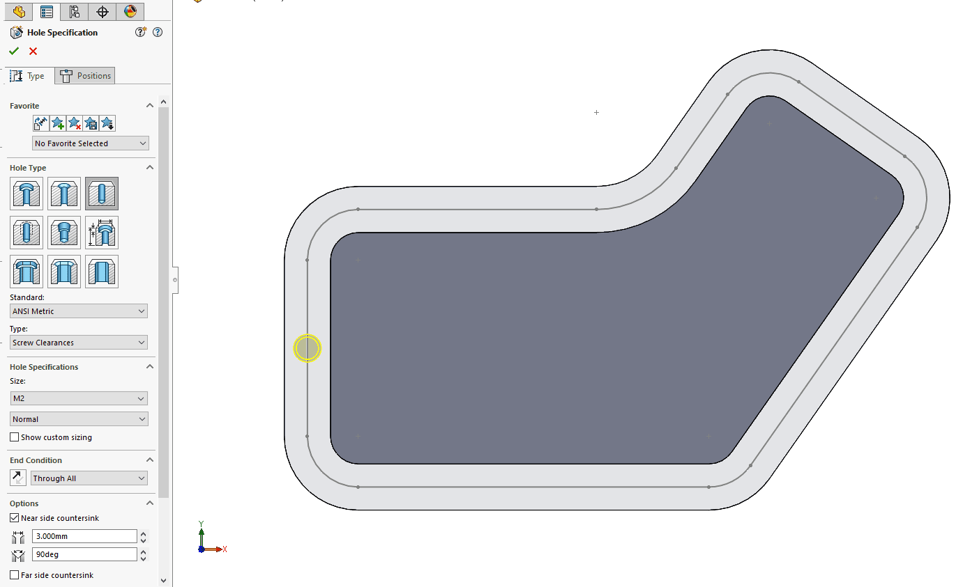
Next, we need to exit this sketch and go create our hole. Using the hole wizard for an M2 screw, and placing it on the midpoint of the left line segment, works great.
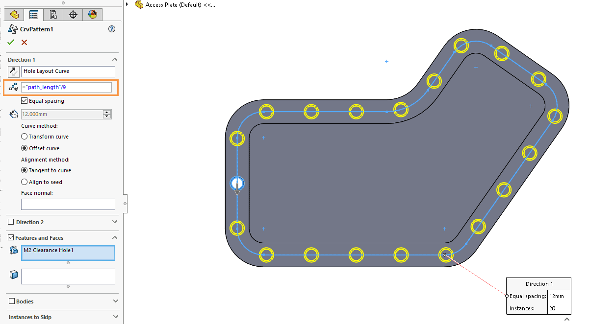
Next, we use the Curve Driven Pattern command to create the additional holes. We set the option for Equal Spacing. In the Quantity parameter, we can hit the “=” key to enter an equation. In this case, the quantity is equal to the global variable “Path_Length” divided by 9.
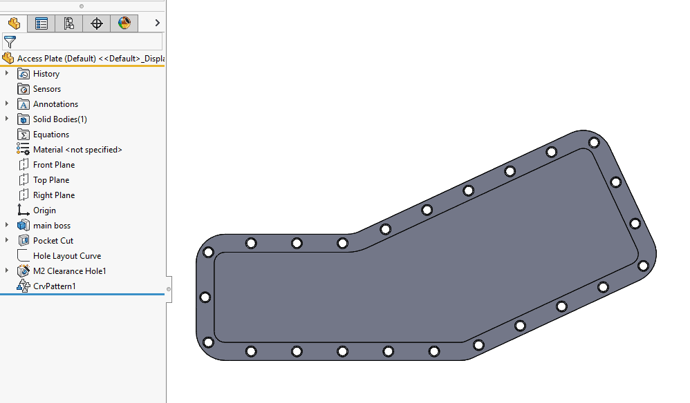
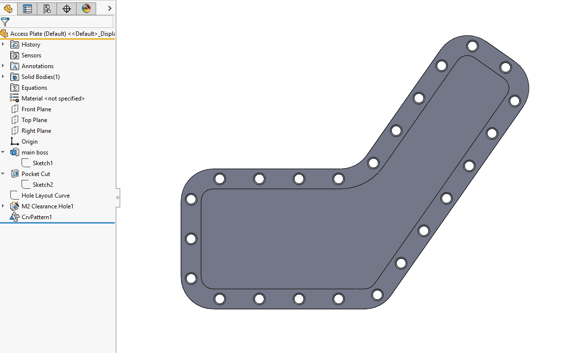
Editing the initial sketch of this part and adjusting its size will make it easy to see how the design intent, “several evenly spaced holes” was captured and maintained through future geometry modifications. Here are two different versions to verify that we were successful.
A bigger and wider version of the part still has several evenly spaced holes around the outer flange.
A taller version of the part also still has several evenly space holes around the outer flange.
Hopefully this example sparks some ideas for where you might be able to take advantage of the Path Length Dimension, Variables, and Equations in your SOLIDWORKS designs.
Greg Buter
Managing Application Engineer
Computer Aided Technology

 Blog
Blog