SOLIDWORKS Electrical Series, #1
With the release of SOLIDWORKS Electrical, users can now create simple or complex electrical schematics and effortlessly integrate your electrical system into your 3D design. Electrical has several capabilities that enable these tasks, such as the single-line schematic planning tool, multiline schematic creation, symbol libraries, and 3D integration tools. Over the next several weeks, I will explore some of these new tools and show how these capabilities are used. For this blog, we are going to look at one of the integrated drawing tools and show you that a line really isn't just a line anymore.
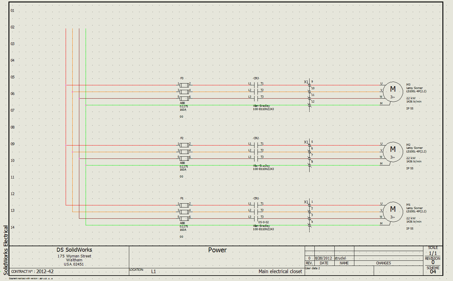
To begin with, let's take a look at the schematics we can create in Electrical and then be able to dive into their creation using lines and symbols.
These drawings can be used at any stage of the development process for product design and provide detail for our design. Using single-line schematics, we can use images of components or symbols, to create simplified representation of the electrical system design. These schematics are then used for your product definition for project planning, fabrication and reporting.
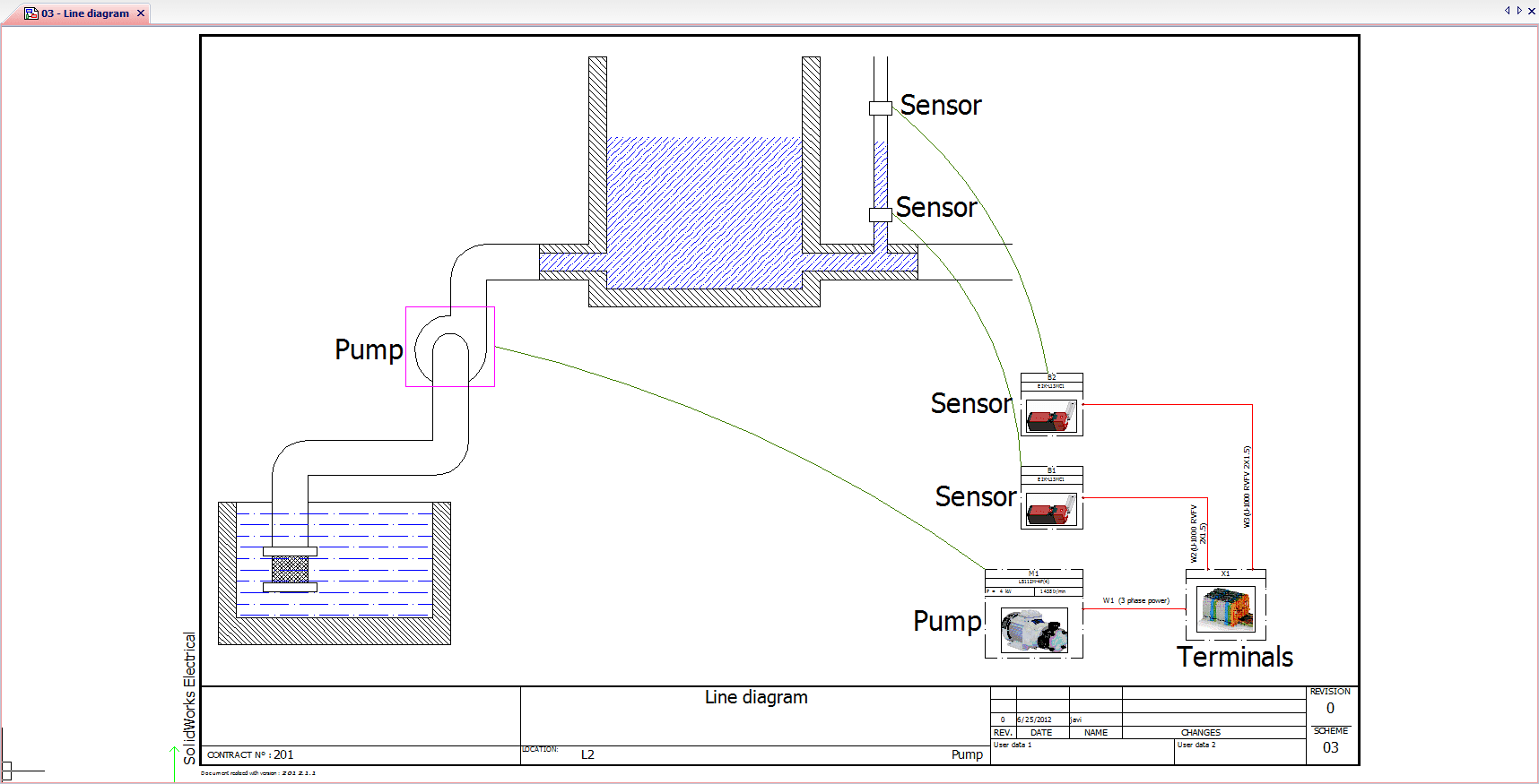
Using the multi-line schematic, we can also quickly create simple yet powerful representations of the electrical wiring and cabling between the various electrical subsystems, equipment and interconnects
Now we can move on to how we can create single lines in a schematic. In the picture, we have a bunch of symbols on our schematic and need to create the connections to these symbols. Using the "draw cable icon", we can draw a line or cable, to add a connection between the parts regardless of location within the design.
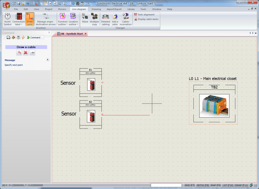
One of the most important features to point out, is that these design elements are smart objects: Meaning that if you resize this wire, copy it and connect it to the original one, it will become a unified single wire, eliminated the need to trim and delete joined wire sections
In addition cables and wires can be assigned from within the single line schematic, since the line diagram is bi-directionally linked directly to the detailed schematics, meaning that all the information entered at this level will be propagated automatically to the rest of the project.
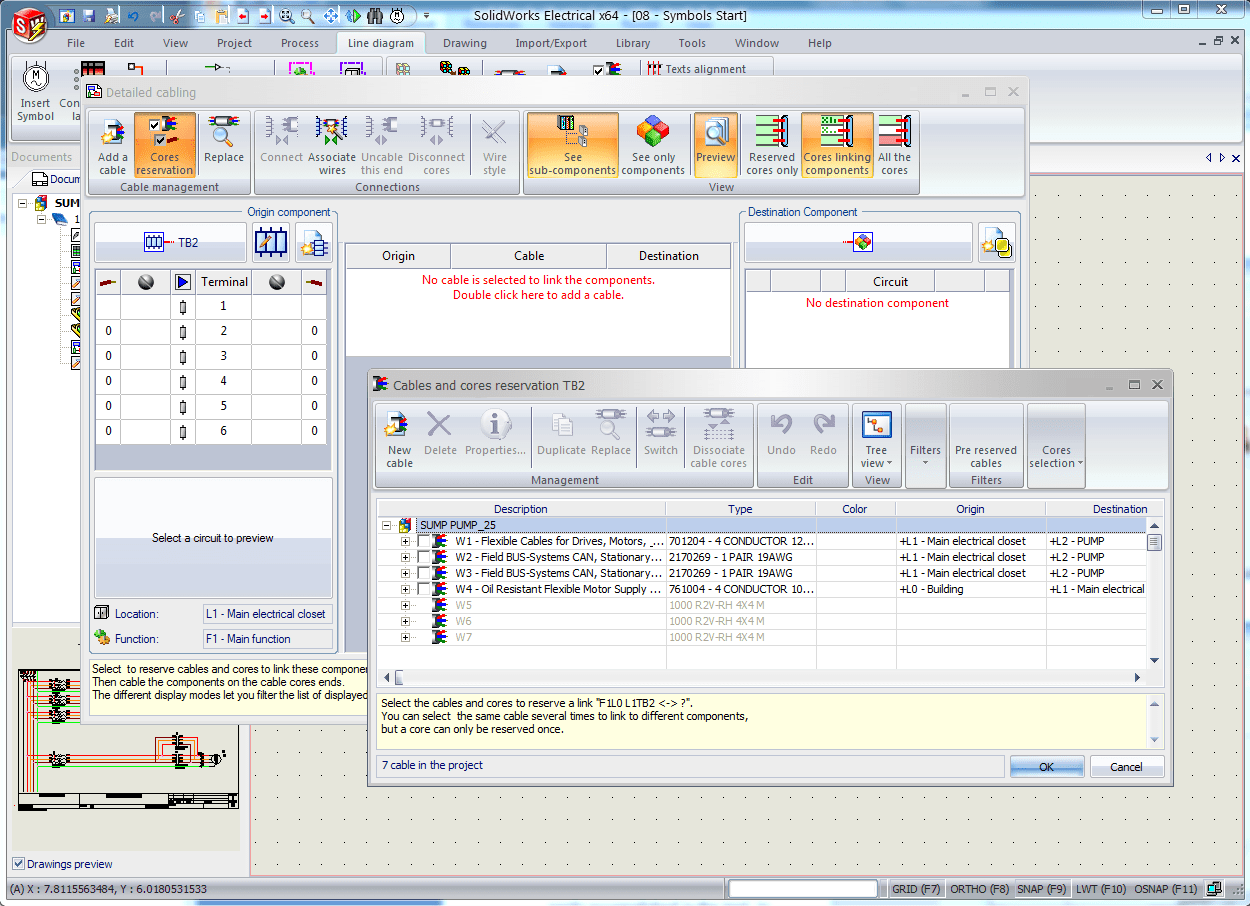
We can predefine cabling in our design environment to quickly specify certain cables or types of wires that we use at the manufacturing stage. This allows us to quickly add information to our schematic.
For a multiple wire line creation, we can select the appropriate style from wire from the Wire Style Selector and then simply pick the wires desired. To further simplify the design process, the drawing of multiple wires is quite easy and requires only a few clicks.
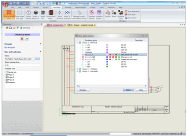
Wire bends are inserted automatically and additional options are also available to the user. If you want to change between angled multiple phase wires or straight point to point wires, that task is easily accomplished in the tool. In addition the conductors can be inverted to increase design flexibility.
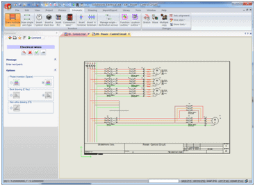
SOLIDWORKS Electrical is powerful 2D schematic software. However, some information like cable and wire lengths can't be calculated in a 2D environment. The lines that we have created are just the begging of our details to our electrical design. Next week we will take a look at the symbols library and how we can connect that information with 3D models and manufacturing information that we can leverage for reports, drawings and other aspects of our design.
Corey Kubichka | Electrical Product Manager

 Blog
Blog