Solidworks Electrical: Import a BOM to start a project
Sometimes your project workflow may be such that it starts with a Bill of Material. For that, SOLIDWORKS Electrical has the “Import Data” feature. This populates the component tree of your project in an easy, quick and simple way.
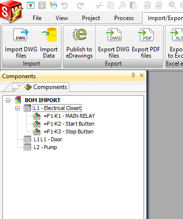
Start with creating your BOM in Excel. It can be saved in xls or xlsx format. Then run the “Import Data” command found on the Import/Export tab in SOLIDWORKS Electrical.

By selecting this option, you go through the following steps.
Start by selecting the data source. Pick either the excel icon or notepad icon depending on the source file format. Find the file, then hit Open.
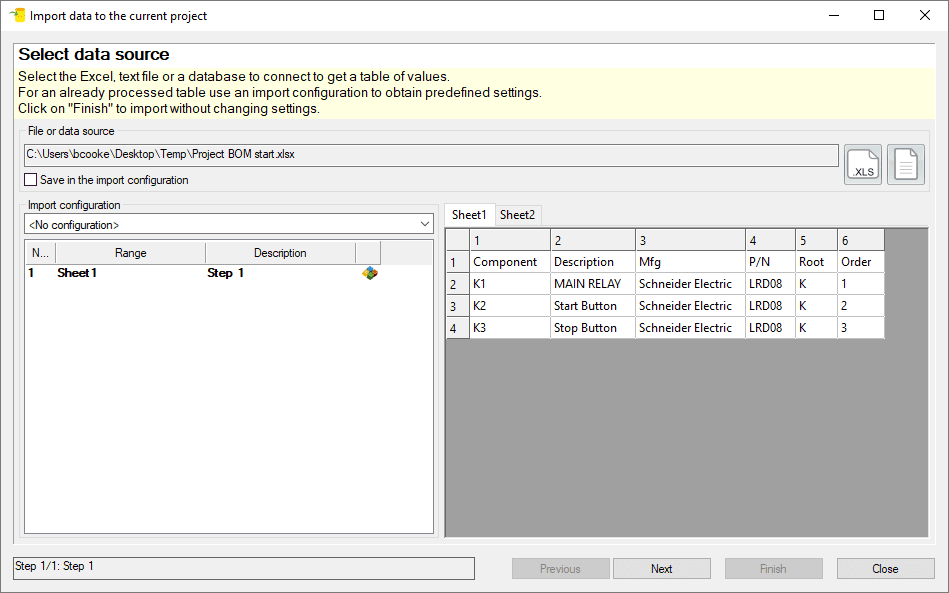
Next you must define the data range and the data type to be imported into the project. In this case, we are importing a list of components, so select the “component” type and the Excel sheet where the Bill of Material data is located.
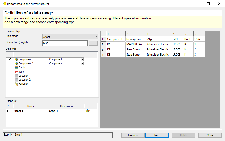
Next, it is necessary to mark the title row as the header of the columns, of this materials list.
In addition, the fields’ mapping will be required. In this dialog box the correlation between BOM’s columns and the SOLIDWORKS Electrical components fields will be established. It is very simple; just select the correct component’s field and drag it from the left side list to the correct BOM column on the right. The assignment between SOLIDWORKS Electrical components and the BOM’s columns will be seen in the object and field rows. If you make a mistake, just start the selection of the field again.
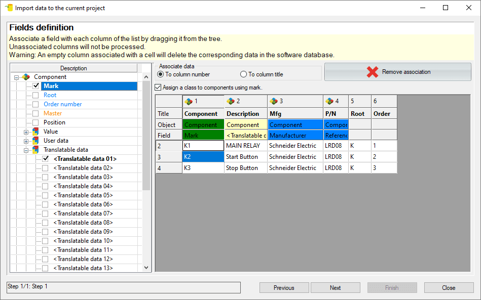
Note that the component description corresponds to Translatable Data 01, even if you have multiple languages. You’ll use this same component field for each different language description by selecting the correct language in the drop-down menu that appears after you have designated the match.
If you have configured the languages correctly in the Project Configuration, you will have the option to select the correct language for each component description, during the drag and drop operation, to make the association.
After this mapping process, in the next dialog box, click on “Compare” button. This produces a text file where you can see the number of the components which will be added in the project’s component tree and all the component tags and their descriptions.
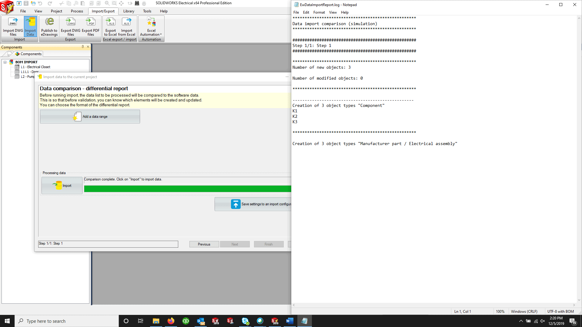
Note: If you include manufacturer and reference information in the import process be sure that the information in the excel file matches with the information in SOLIDWORKS Electrical library.
If not, the references will be created only at project level and without the library properties.
After the compare process finishes, the button will change to say “Import.” Select that button to finish the import process. The components should now be in your project component tree with their tags and descriptions in the corresponding languages. They will be placed in the default location and function.
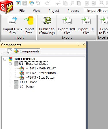
After importing, you can select any components you’d like, and change their location and/or function as necessary.
If you need a personalized project structure, with the components placed directly in the correct location and in the correct function, the import excel file can be prepared with separate sheets, one for functions, second for locations and a third for components. For this you need to start with the mapping of functions and locations first and then do the mapping for components in the same import process.
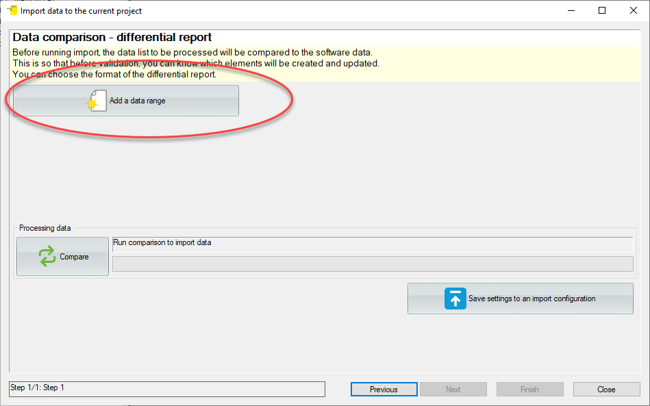
After mapping the functions fields, in the last step instead of selecting compare, select “Add a data range”. You’ll next add functions. Then add data range to finally add the components.
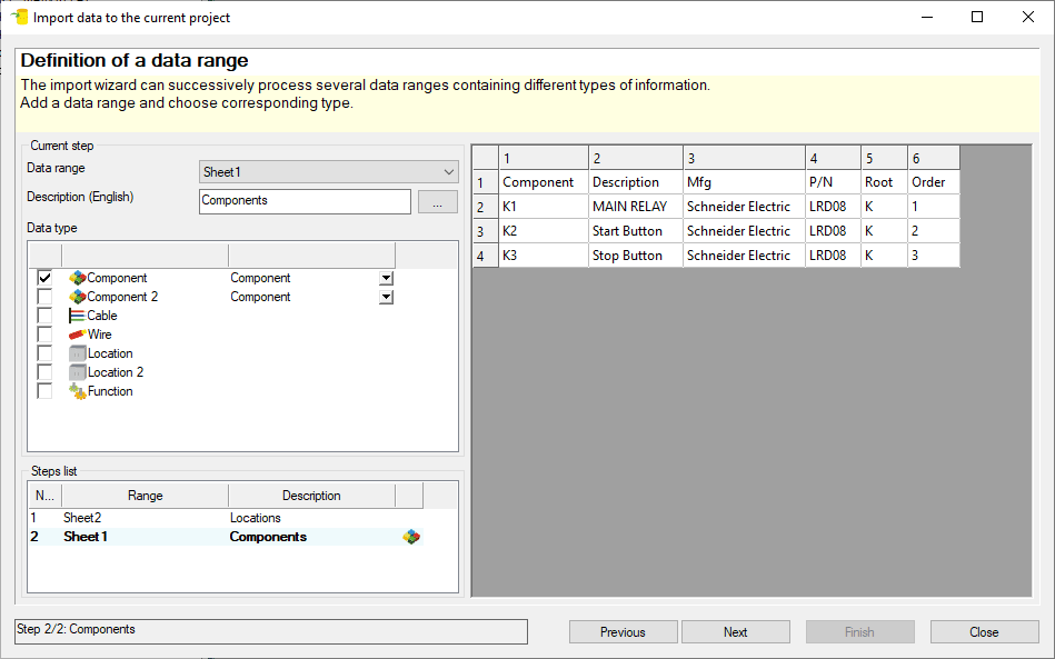
Although the locations and functions were defined on their own sheets, you’ll still need columns to define which locations correspond to which components on the component tab in excel. So when you run through the component step of the import wizard you can match the columns to the fields on the left.
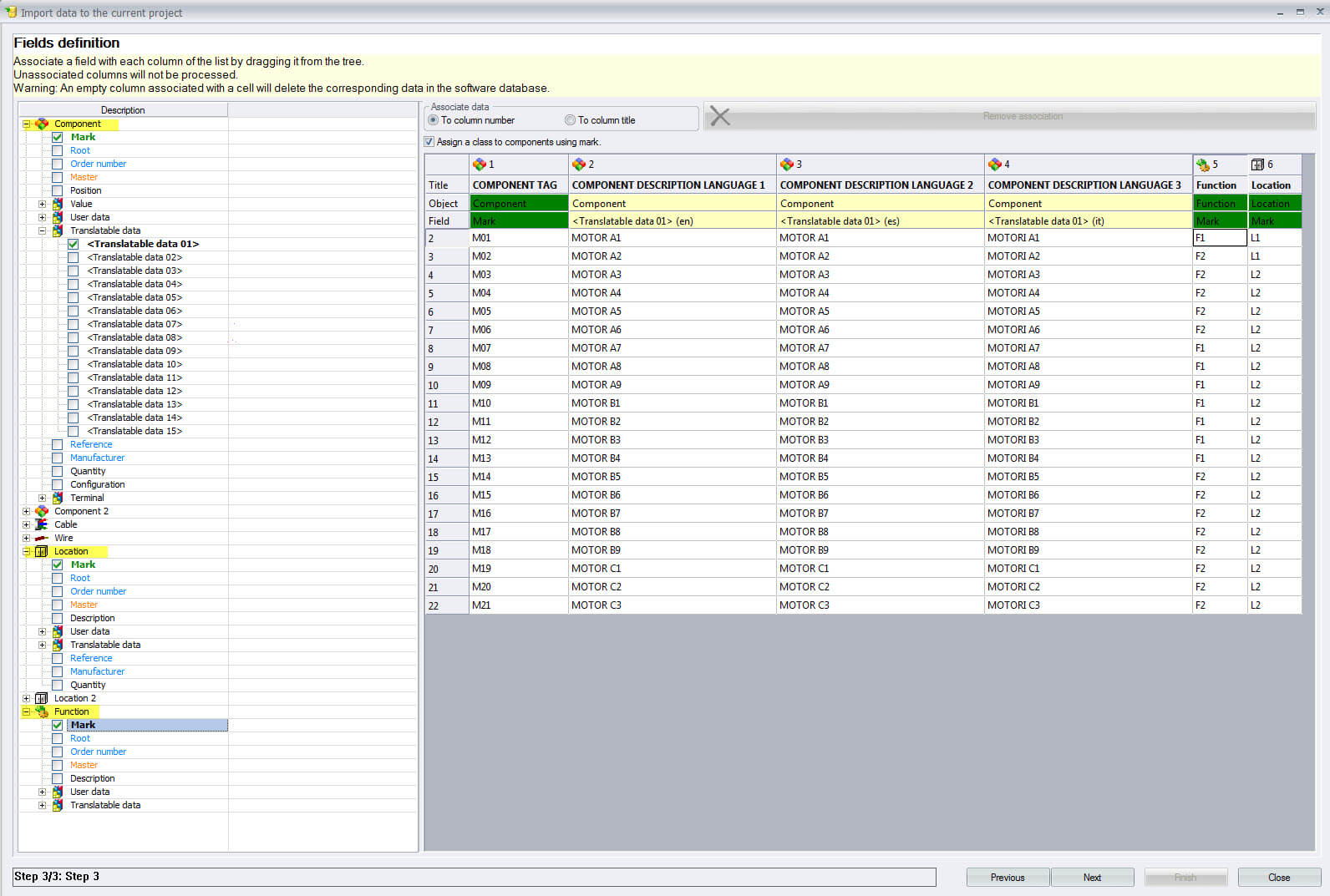
Now, you “Compare” and then “Import”.
With the components tree created, you can create all the reports that you need, assign manufacturer parts references from your libraries and insert the components in a drawing as symbols, by using a right click on a component and then selecting the option “insert symbol”.
This is one option that can reduce the number of errors in your project, improving efficiency and finishing projects faster to increase the benefits of the software.

 Blog
Blog