SOLIDWORKS 2021 What’s New – Visualize Displacement Mapping
Visualize keeps getting better and better every year, and SOLIDWORKS Visualize 2021 now includes a new type of texture mapping that will allow you to create even more stunning renderings! Displacement!
This type of texture uses a height map to create sub-polygon detail for any appearance. SOLIDWORKS 2019 saw an enhancement that uses the same height map images using the 3D Texture Feature, but now you can render your models without needing to create a mesh model in SOLIDWORKS first!
In Visualize, on the Texture tab, you will see there is a new Type list that includes an option for Displacement when selecting or adding an image for bump.
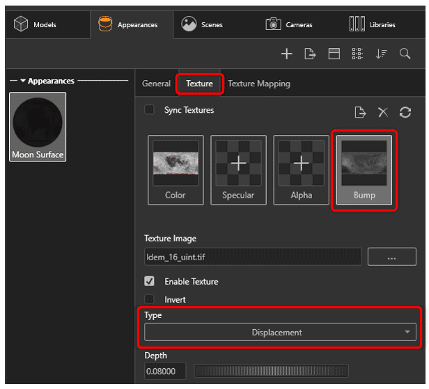
On the Texture Mapping tab, there is a new Displacement Density field that controls the quality and size of the polygons for the displacement. Higher values here result in better quality, and longer render times.
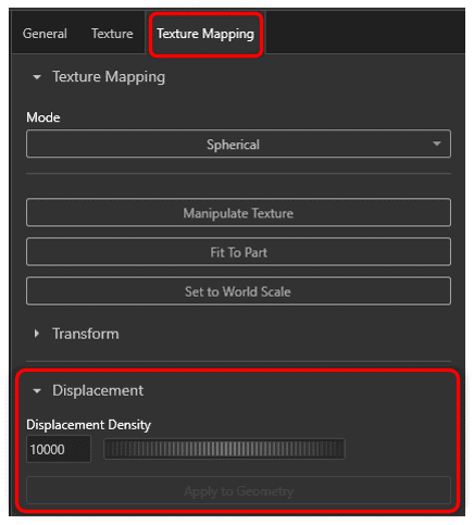
Using these new settings creates some stunning results! Below you can see the difference that displacement mapping adds to a simple sphere.
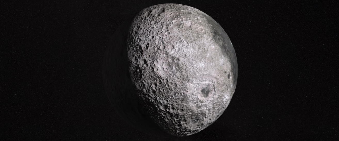
Before: Normal map
After: Displacement Map
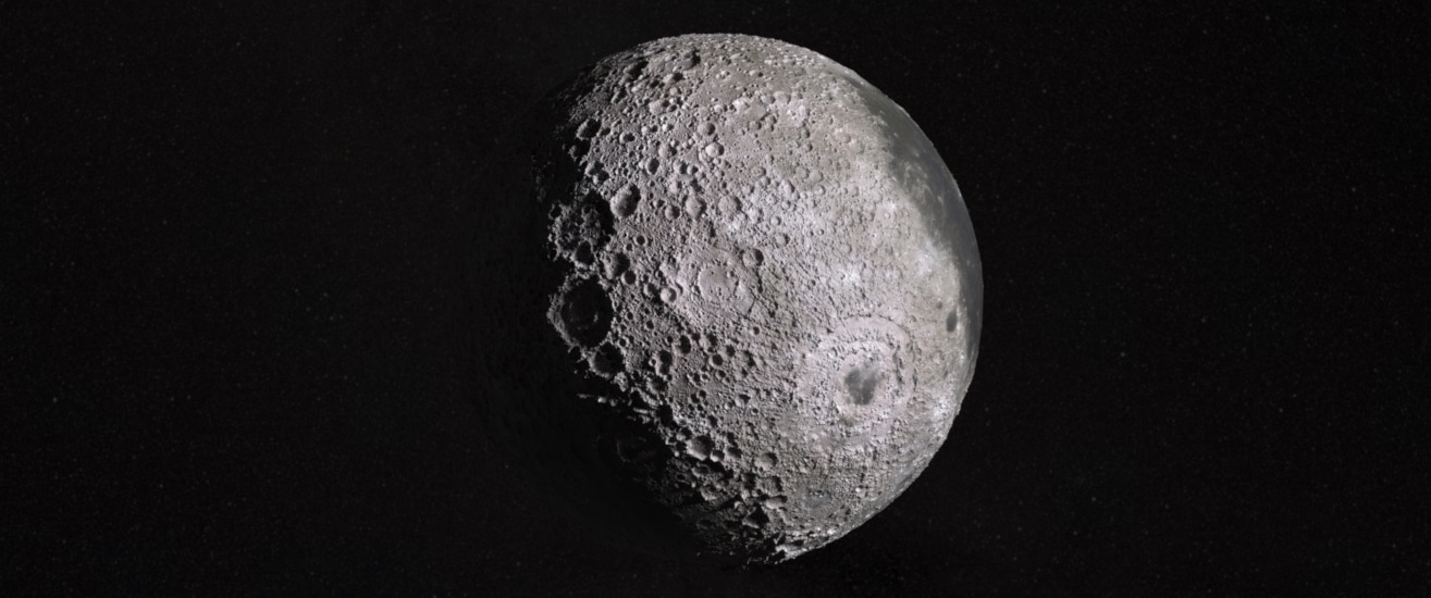
Notice the difference in the shadows that are produced. The displacement map creates new polygons with real height. The shadows are much more accurate, and different heights in the surface can be observed around the silhouette of the sphere. Normal maps only simulate the effect that the light would have without any real difference in surface height. As a result, the normal map suffers around the same areas mentioned above. The settings I used can be seen in the screenshots above. All texture and height map data used here came from NASA’s Scientific Visualization Studio. https://svs.gsfc.nasa.gov/4720.
Extra Credit:
So how can I create my own height maps you ask? With SOLIDWORKS and Visualize!
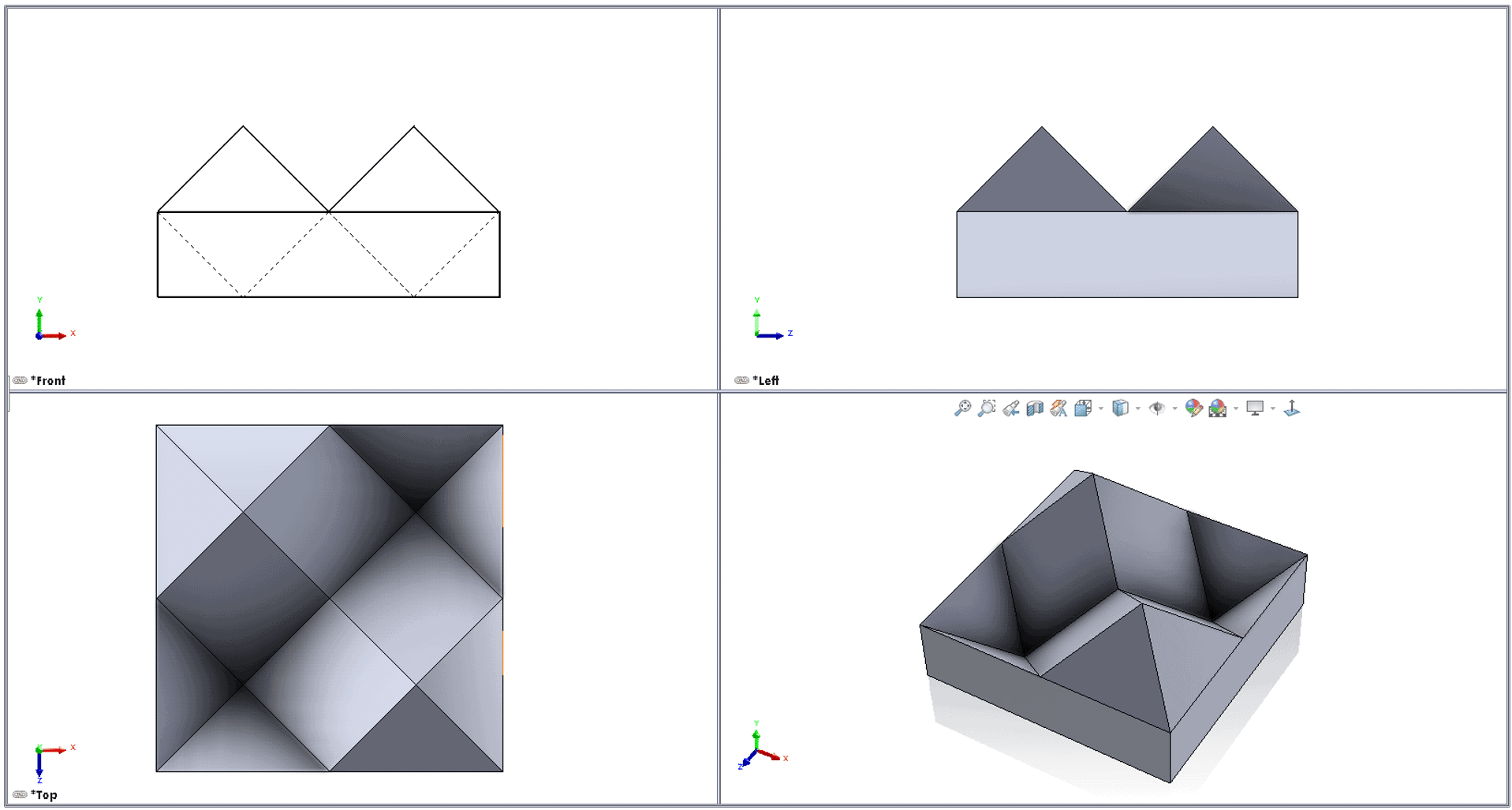
Using SOLIDWORKS I created a new model I wanted to use for a new displacement map.
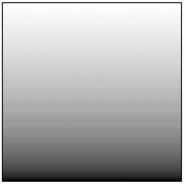
After importing the model into Visualize, I added a gradient 80% grey to black color to the model, using planar projection along the x-axis, through the part. The appearance type is set as “flat” so that no shadows, shading, lighting, or environment effects can be seen, only the original color from the gradient image.
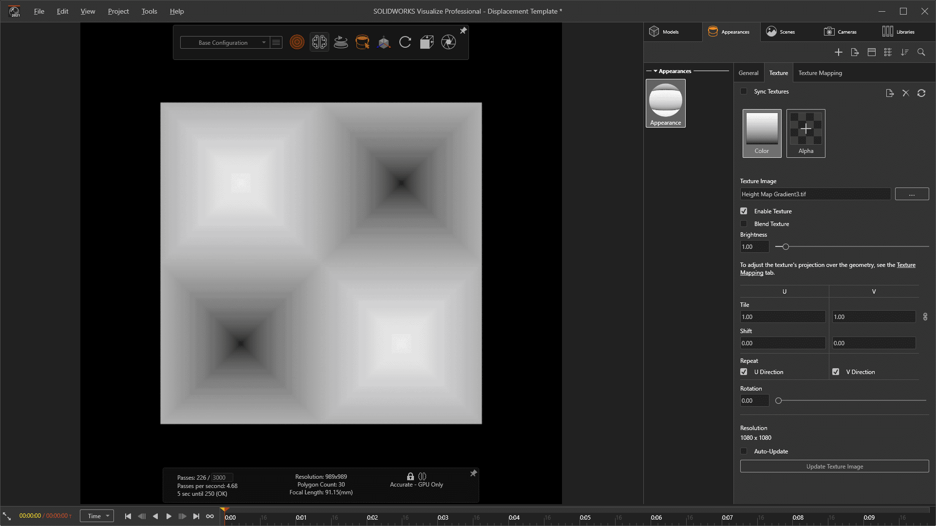
The result is grey at the peaks and black at the bottom.
Now that the appearance is setup, I created an orthographic camera looking directly down on the object through the y-axis as seen above. The project can then be rendered out to tiff and cropped to the boundary of the texture. This image can now be applied in other visualize projects as a displacement map. As a bonus, these image textures can also be used in SOLIDWORKS with the 3D Texture tool if you needed to 3D print a part.
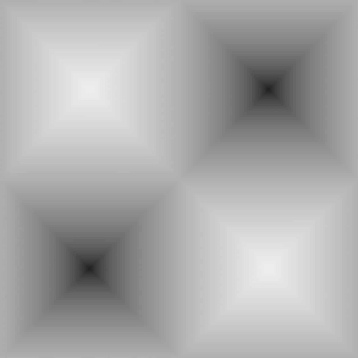
Download this Displacement map
Below you can see the new displacement map applied to a few different shapes in Visualize.
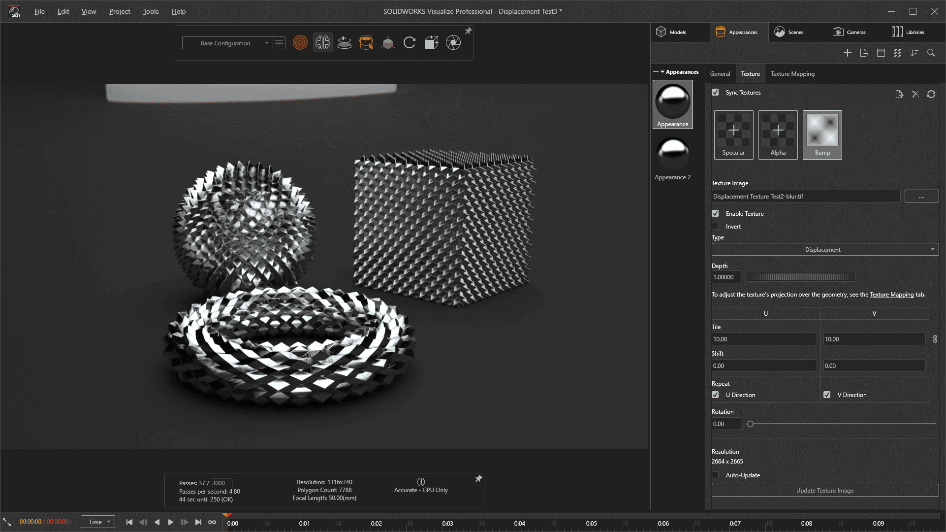
Download this Visualize Project
I hope this part of the What’s New series gives you a better understanding of the new features and functions of SOLIDWORKS 2021. Please check back to the CATI Blog as the CATI Application Engineers will continue to break down many of the new items in SOLIDWORKS 2021. All these articles will be stored in the category of “SOLIDWORKS What’s New.”
Alex Worsfold
Sr. Application Engineer
www.cati.com
What is DI Month? We’re declaring October Design Innovation Month—again! It’s a month-long series of special events focused on what’s new in design and manufacturing technology. You’ll learn about enhancements in SOLIDWORKS 2021 that deliver new capabilities for improved performance, streamlined workflows, and a connected design ecosystem. Find out what’s new in 3D printing applications and 3D scanning to integrate into your design process.

 Blog
Blog 