SOLIDWORKS 2021 What’s New – SIMULATION Contact Terminology Changes
If you have read through the What’s New document for SOLIDWORKS 2021, I am sure you noticed the many updates and improvements listed for SOLIDWORKS Simulation. Blog title aside, if you think this is only about terminology changes, think again! I can assure you nomenclature is only a part of what I will describe for SOLIDWORKS Simulation 2021. If you want to know more about this topic, start with my colleague Matt Sherak’s blog Understanding Contact Hierarchy in SOLIDWORKS Simulation. While I am tempted to re-write (not plagiarize!) his blog, there is more than just name changes in SOLIDWORKS Simulation 2021.
Let’s start with the obvious terminology changes. What was formerly referred to as ‘contact’ is now called ‘interaction’. The term ‘no penetration’ is now called ‘contact’. Finally, what was ‘allow penetration’ is now called ‘free’. The beginning of terminology changes for ‘Component Contacts’, now ‘Component Interactions’, can be seen in Figure 1. If you have used other FEA codes, then you know that SOLIDWORKS Simulation’s old terminology was not the norm. The simple takeaway is these changes align terminology with industry standards.
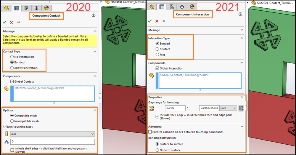
Figure 1
There are a few other items to note regarding Figure 1. The order of Interaction Types has changed in SOLIDWORKS Simulation 2021; Bonded is now at the top of the list and Contact has moved to the second item in the list. The bottom section of the Property Manager has the most significant change – more than just names! The terms ‘compatible’ and ‘incompatible’ were unique to SOLIDWORKS Simulation and did not describe what was occurring at the mesh level. A ‘compatible’ mesh was used to enforce common nodes across touching boundaries of parts and was the default option for SOLIDWORKS Simulation 2019 and prior. Starting with SOLIDWORKS Simulation 2020, the default was an ‘incompatible’ mesh, which did not enforce common nodes between coincident component faces. New meshing and bonding algorithms improved the accuracy of meshes without enforced common nodes and began with last years’ SOLIDWORKS Simulation 2020 release.
One of the most significant changes to the Component Interaction Property Manager is in the Properties section. Gap Range for bonding is a massive addition to Global Interactions. For years I have preached that users need to clean up their SOLIDWORKS CAD models prior to starting any analysis work – remove interferences, close small gaps, and much, much more. Now I am not going to completely back off on CAD cleanup, however, this new Gap Range for bonding reduces the need to make bodies face-to-face coincident in the CAD model prior to beginning analysis work. The 0.01% is the default value and can be set as a SOLIDWORKS Simulation Option (more on that later). This calculates a characteristic length of the CAD model and expands the influence of the specified Global Interaction between the near-touching faces of components. Finite element models with small gaps that would either solve incorrectly or fail in Linear Static analysis with only Global Bonded Interactions (formerly Global Bonded Contacts) will now solve without adding Local Interactions (formerly Local Bonded Contacts). Gap Range for bonding is on by default in SOLIDWORKS Simulation 2021. Did I mention this change was significant? Pretty sure I did! (This could be accomplished in prior versions of SOLIDWORKS Simulation, provided the user applied the correct non-touching faces settings. This will be discussed in greater detail in a later What’s New in Simulation 2021 blog!)
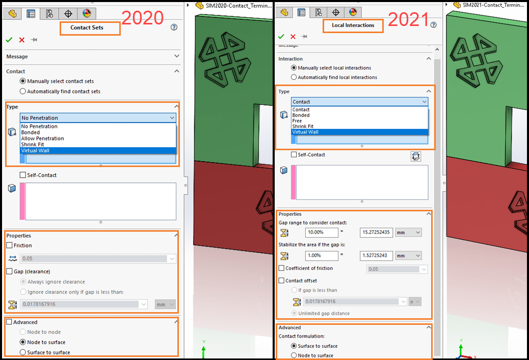
Figure 2
SOLIDWORKS Simulation users will notice the second terminology change in the Local Interactions Property Manager (formerly Contact Sets); reference Figure 2. The previously mentioned terminology changes are propagated to the type of Local Interaction that users select. The Properties section of Local Interactions adds additional options for contact stabilization. Contact stabilization adds a small stiffness to regions of components before they come into contact. Also, what used to be called ‘Gap (clearance)’ is now named ‘Contact offset’. If this option is enabled, what was termed ‘Always ignore clearance’ is replaced with ‘Unlimited gap distance’. If you want to understand these options, I recommend reading the Help Files which are current for the SOLIDWORKS Simulation 2020 release. (Contact Stabilization will be discussed in greater detail in a later What’s New in SOLIDWORKS Simulation 2021 blog.)
The next terminology change is visible in Figure 3. The terminology changes are propagated to the SOLIDWORKS Simulation Feature Tree for several items – local interactions, component interactions, global interactions, independent mesh, and the Interaction Viewer (formerly Contact Visualization Plot).

Figure 3
Figures 4 and 5 contrast the differences between the Contact Visualization Plot (SOLIDWORKS Simulation 2020) and the Interaction Viewer (SOLIDWORKS Simulation 2021).
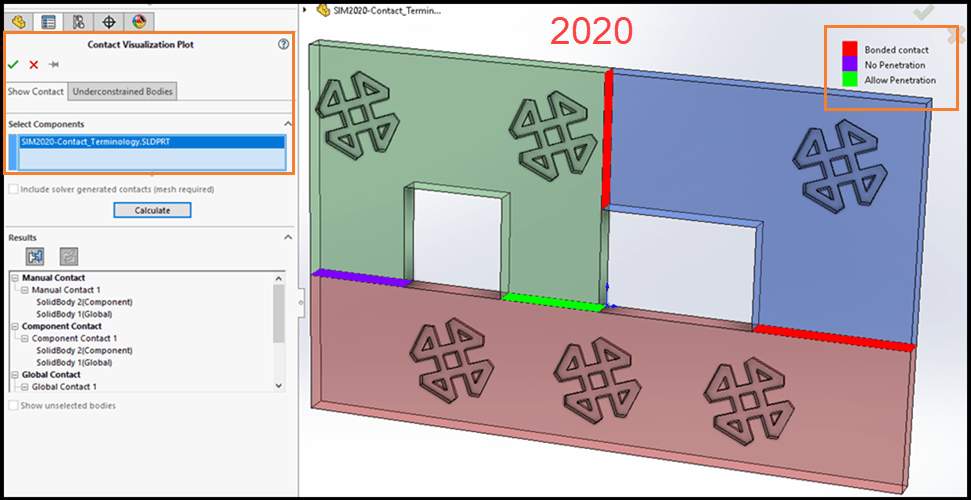
Figure 4
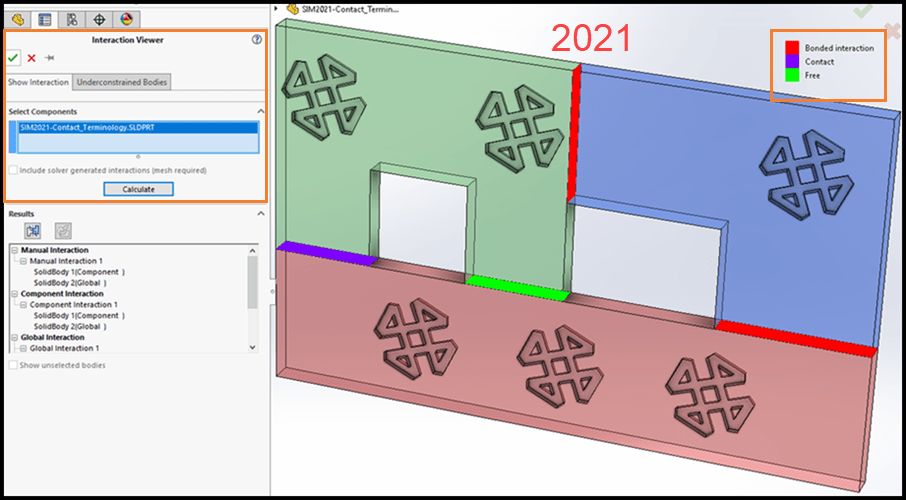
Figure 5
The last section of terminology changes to discuss are found in the SOLIDWORKS Simulation Options, reference Figure 6. In SOLIDWORKS Simulation 2020, the Default Options… Contact section was sparse with only two selections available. On the left side of the figure I had checked the option to create a compatible mesh. As previously mentioned, this was not the default for SOLIDWORKS Simulation 2020. The second item is the ‘Show advanced options…’ radio button, which I would always instruct SOLIDWORKS Simulation users to turn on.
In SOLIDWORKS Simulation 2021, there are many changes in the Options interface. The Global interaction type section allows users to select the default for Linear Static studies. In SOLIDWORKS Simulation 2020 and prior, the default was bonded and could not be pre-selected. The Properties section allows users to specify the default percentage for ‘Gap range for bonding’, previously discussed referring to Figure 1. The lower portion of the Properties section sets the default values for Local Interactions and Contact Stabilization. The Advanced section allows users to choose ‘Enforce common nodes…’ (formerly compatible mesh) as the default. The ‘Show advanced options…’ radio button has been removed from the Default Options interface and is now always active. Finally, the default options for Contact formulation and Bonding formulation can be specified by the user. Astute users may notice that the option ‘Node to Node’ is not shown in the Contact formulation section. “Node to Node” formulation has been removed as an option from SOLIDWORKS Simulation 2021. “Node to Node” formulation will be replaced with “Node to Surface” formulation when working on legacy studies in SOLIDWORKS Simulation 2021 and forward.
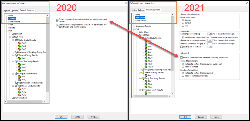
Figure 6
Aside from making SOLIDWORKS Simulation 2021 terminology changes align with industry standard nomenclature, I hope you understand that this was more than just name changes. In some instances, significant functionality was added to our analysis capabilities. In other instances, common options that users routinely had to activate have become the norm. What other changes to SOLIDWORKS Simulation 2021 are you most excited about? New meshing technology? Solver performance? All of them! Awesome. Now go make your products better with SOLIDWORKS Simulation!
[Screen captures for this blog are from SOLIDWORKS Simulation 2021 Beta 3.]
I hope this part of the What’s New series gives you a better understanding of the new features and functions of SOLIDWORKS 2021. Please check back to the CATI Blog as the CATI Application Engineers will continue to break down many of the new items in SOLIDWORKS 2021. All these articles will be stored in the category of “SOLIDWORKS What’s New.”
Bill Reuss
Sr. Simulation Product Specialist
www.cati.com
What is DI Month? We’re declaring October Design Innovation Month—again! It’s a month-long series of special events focused on what’s new in design and manufacturing technology. You’ll learn about enhancements in SOLIDWORKS 2021 that deliver new capabilities for improved performance, streamlined workflows, and a connected design ecosystem. Find out what’s new in 3D printing applications and 3D scanning to integrate into your design process.

 Blog
Blog 