SOLIDWORKS 2020 What’s New: Simulation - Distributed Coupling for Pins and Bolts
In many FEA studies using SOLIDWORKS Simulation, the use of pins and bolts are common. They are a great way to restrain assemblies realistically while managing setup difficulty and solve times. SOLIDWORKS Simulation 2020 is releasing with a new formulation for bolts and pins, called the distributed coupling. To understand this new functionality, let’s do a quick review of these connectors.

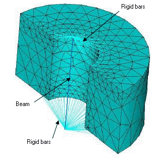
At the end of the day, bolt and pin connectors consist of 2 elements. The first is a beam that goes down through the bolt/pin hole. This is simply a beam element whose mechanical properties are dictated by the material and diameter of the hardware. The second is the rigid bars. These rigidly connect the end of the beam element to nodes that lie inside the bolt’s head and nut diameter, and on any faces given the “tight fit” designation. Pin connectors are very similar, except they tie the ends of the rigid bars to nodes on the inside of the hole the pin lies in. The new distributed connector definition changes the way that these rigid bars transfer loads to the finite element model (FEM) mesh.
Traditionally, these rigid bars are identical, and they evenly distribute the load to all nodes that they are tied to. This can cause singularities due to the inherent added stiffness these bars impose. Instead, the new distributed connector definition allows this load to be dispersed to the nodes more realistically. This decreases singular nodes and provides for more realistic results. Let’s have a look.
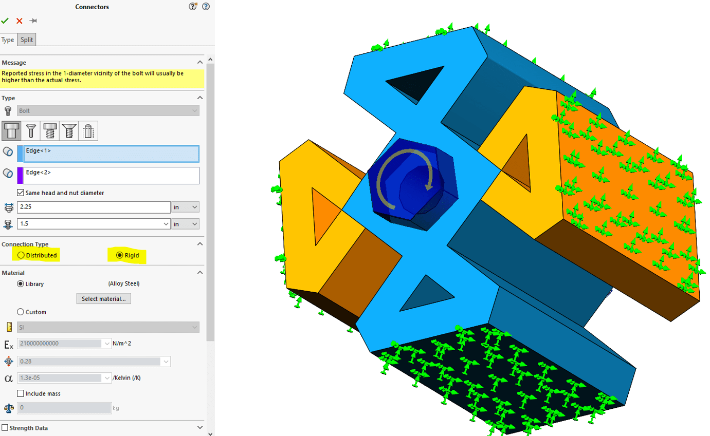
The toggle between the old “rigid” connector and the new “distributed” connector is in the connector definition. Below you can see I have applied a bolt with preload through the center of my CATI part. Proper fixtures and contacts have been applied.

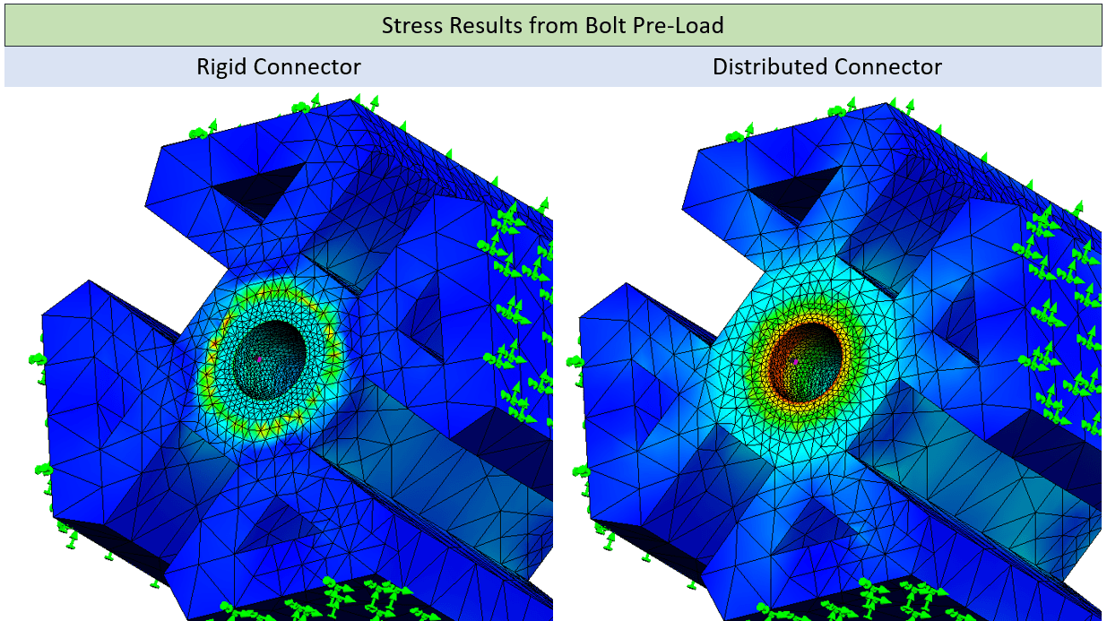
I ran the same analysis 2 times. The only thing I changed from one to the other was the type of bolted connection type. I think the stress and displacement plots say it all.


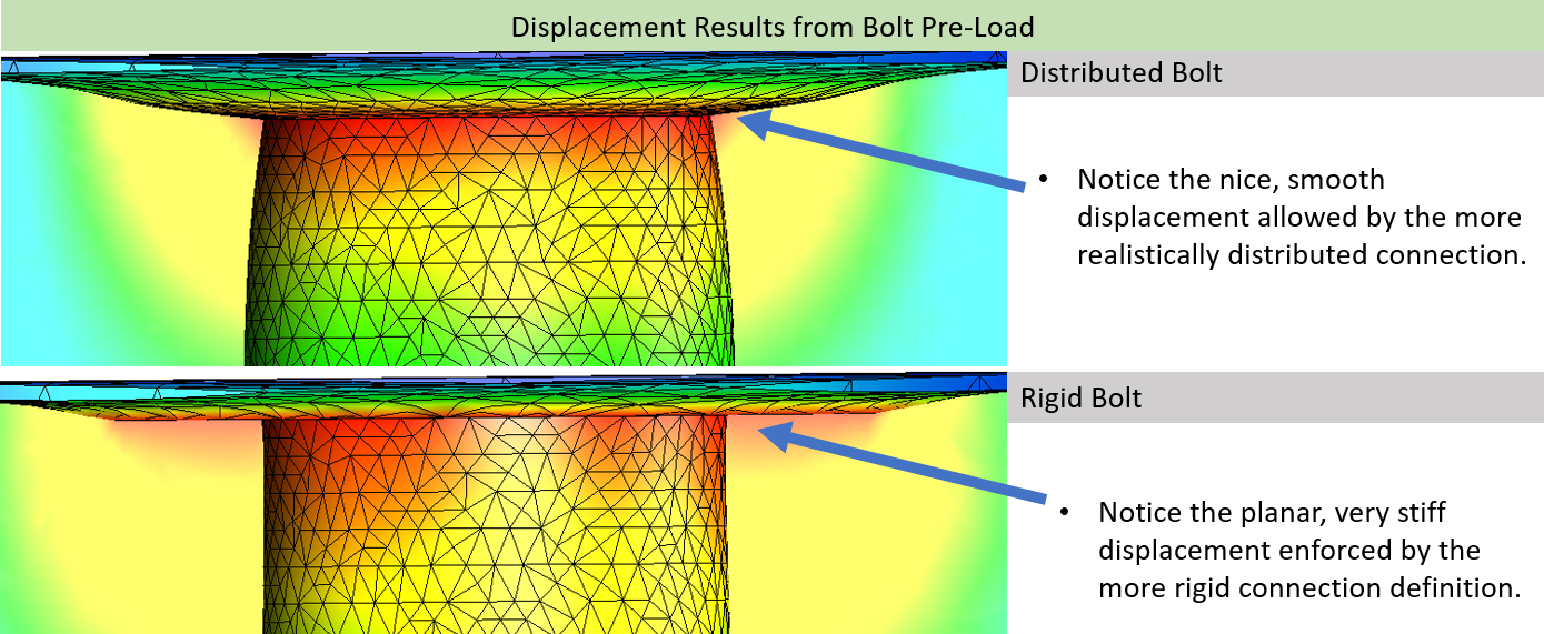
The image above is a cross-section of the bolt hole so we can more easily see the deformation at the bolt’s head. As you can see, the distributed connection is a great improvement! It reduced singular stress nodes induced by the rigid bars and allows for much smoother deformations. The rigid connector forces all nodes to be displaced evenly, which is not realistic.
The distributed connector is available for linear static simulations. It allows for nodes on pin and bolt connections to deform relative to one another instead of being held rigidly. It is just one of the many great improvements in SOLIDWORKS 2020. Take a few minutes and read about some of the other great ways we can help make your designs better with SOLIDWORKS Simulation here.
I hope this part of the What’s New series gives you a better understanding of the new features and functions of SOLIDWORKS 2020. Please check back to the CATI Blog as the CATI Application Engineers will continue to break down many of the new items in SOLIDWORKS 2020. All these articles will be stored in the category of “SOLIDWORKS What’s New.”
Design Innovation Month – October 2019
What is DI Month? We’re declaring October Design Innovation Month—again! It’s a month-long series of special events focused on what’s new in design and manufacturing technology. You’ll learn about enhancements in SOLIDWORKS 2020 that deliver new capabilities for improved performance, streamlined workflows, and a connected design ecosystem. Find out what’s new in 3D printing applications and 3D scanning to integrate into your design process. So, get ready to do things differently. It’s time to innovate!
Matt Sherak
Simulation Product Specialist
Computer Aided Technology, LLC

 Blog
Blog 