SOLIDWORKS 2019 What’s New – Slicing Mesh BREP Bodies Using Planar Entities – #SW2019
SOLIDWORKS 2019 introduces a new feature to help reverse engineer or create sketch references based on a sliced section of a model.
Introducing the Slicing Tool.
You can use the Slicing Tool to create 2D sketch sections at the intersection of your source geometry and a reference plane. This works on standard BREP geometry, the new Mesh BREP geometry, and Graphics Bodies.
In this example, I will show you how you can use the Slicing Tool on this SOLIDWORKS Mesh Body geometry using a planar face reference.
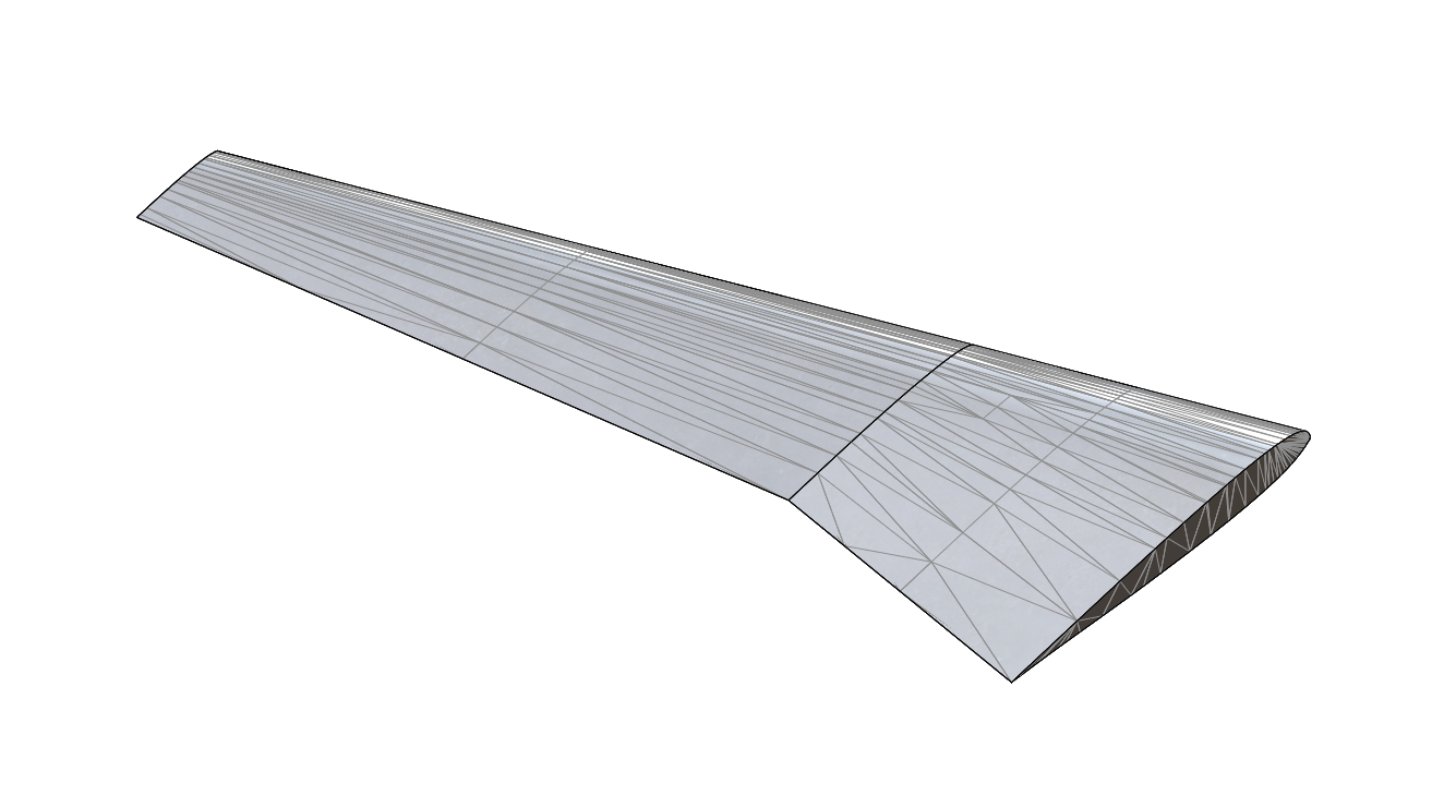
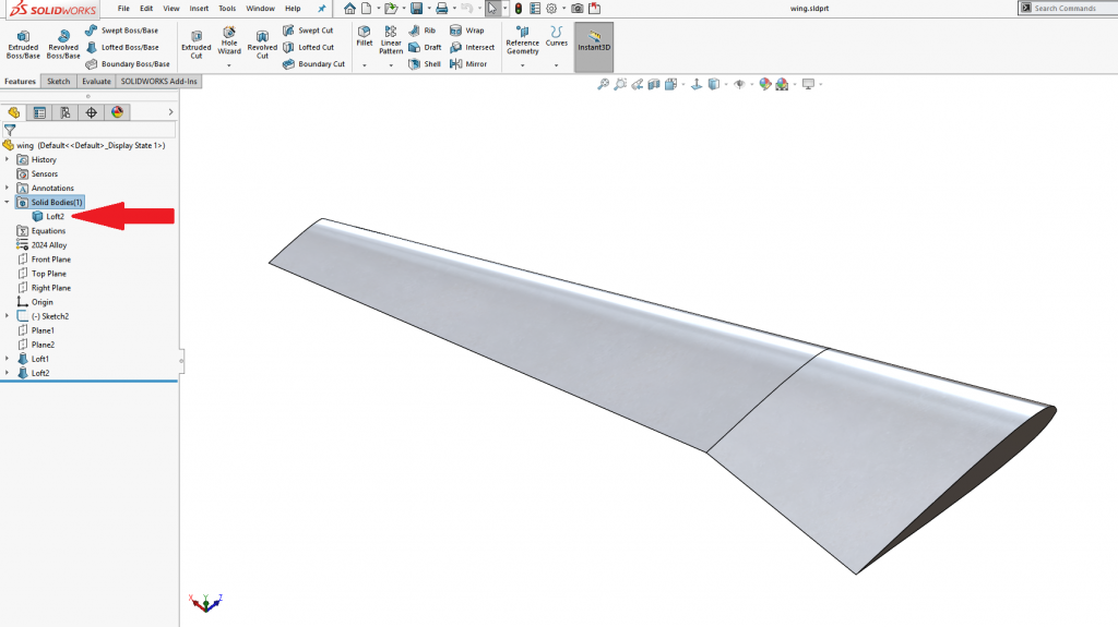
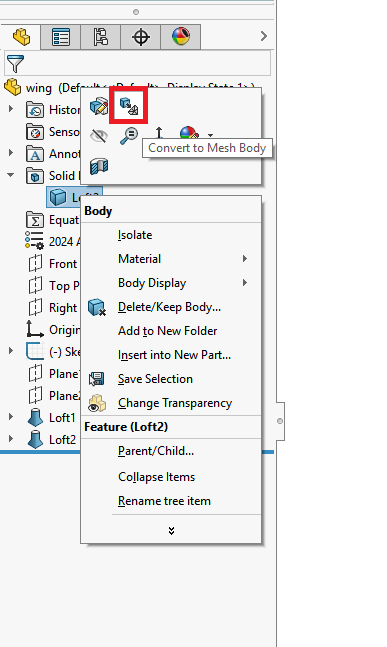
Tech Tip: To convert your standard SOLIDWORKS Solid Body to a Mesh Body, expand the Solid Bodies folder, right click the Solid Body and select Convert to Mesh Body.
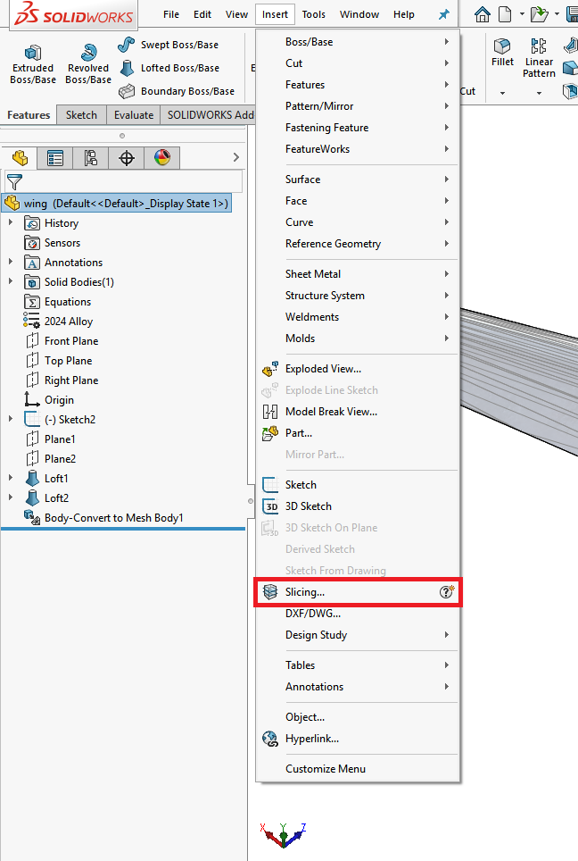
To access this new tool, select Insert > Slicing.
Then, select a planar face or facet as shown.
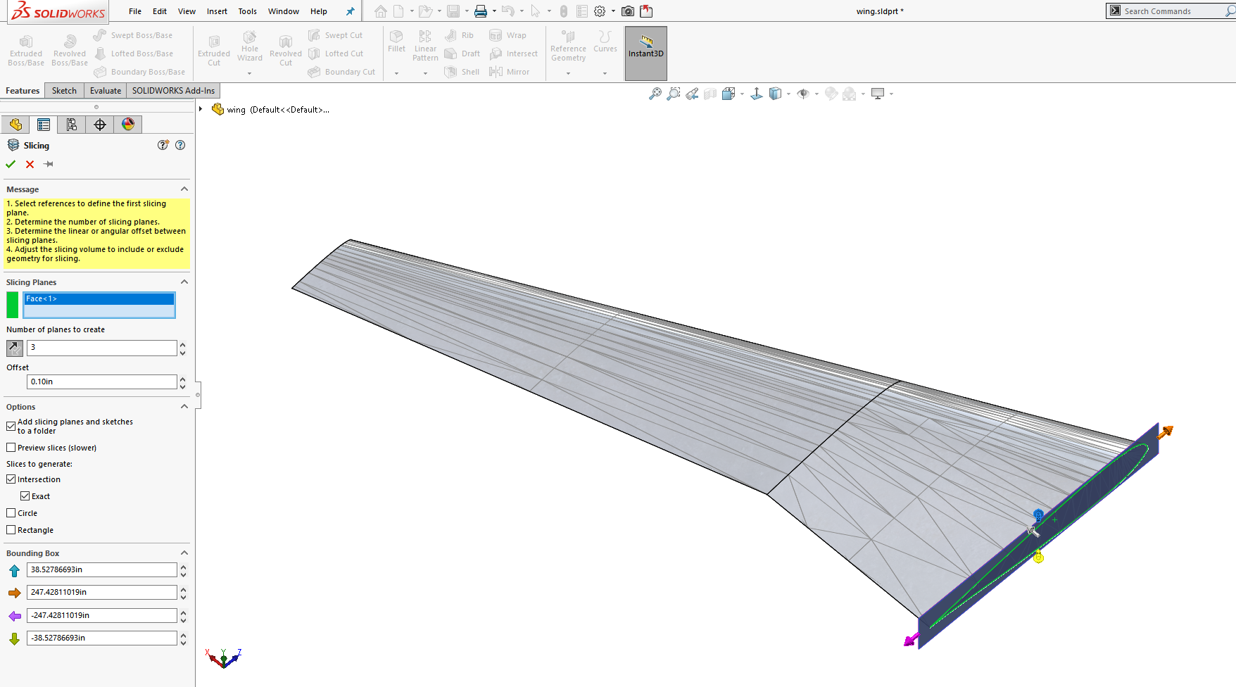
Use the Reverse Direction Arrow to make sure your Slicing Sections are going in the correct direction and set the Number of planes to create and Offset between sections. You can also use the Bounding Box arrows to resize your Slicing area to encompass the entire part as shown.
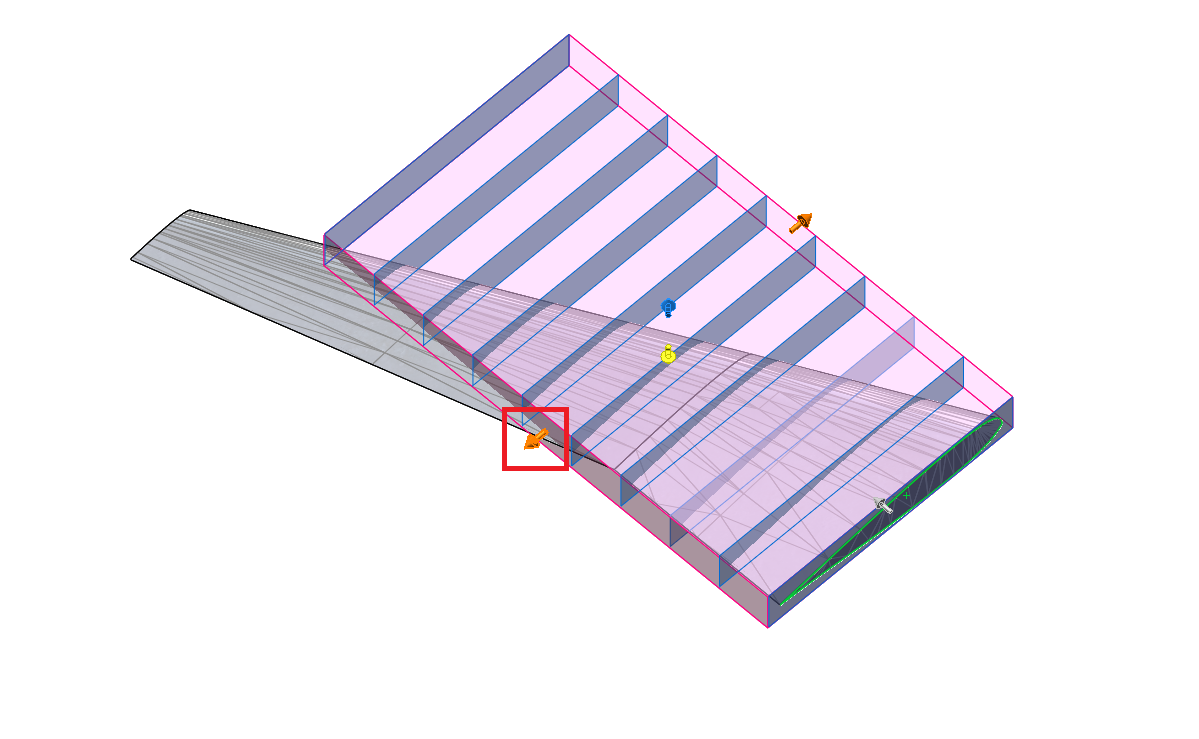
Dragging this arrow will increase the size of the Bounding Box.
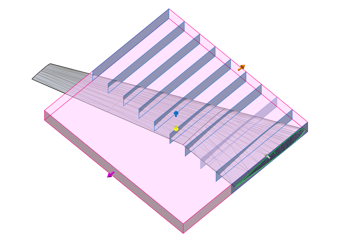
Once you have the desired number of Slicing Sections and the Bounding Box is encompassing the part, you can select Preview in the Property Manager to see the result before completing the command.
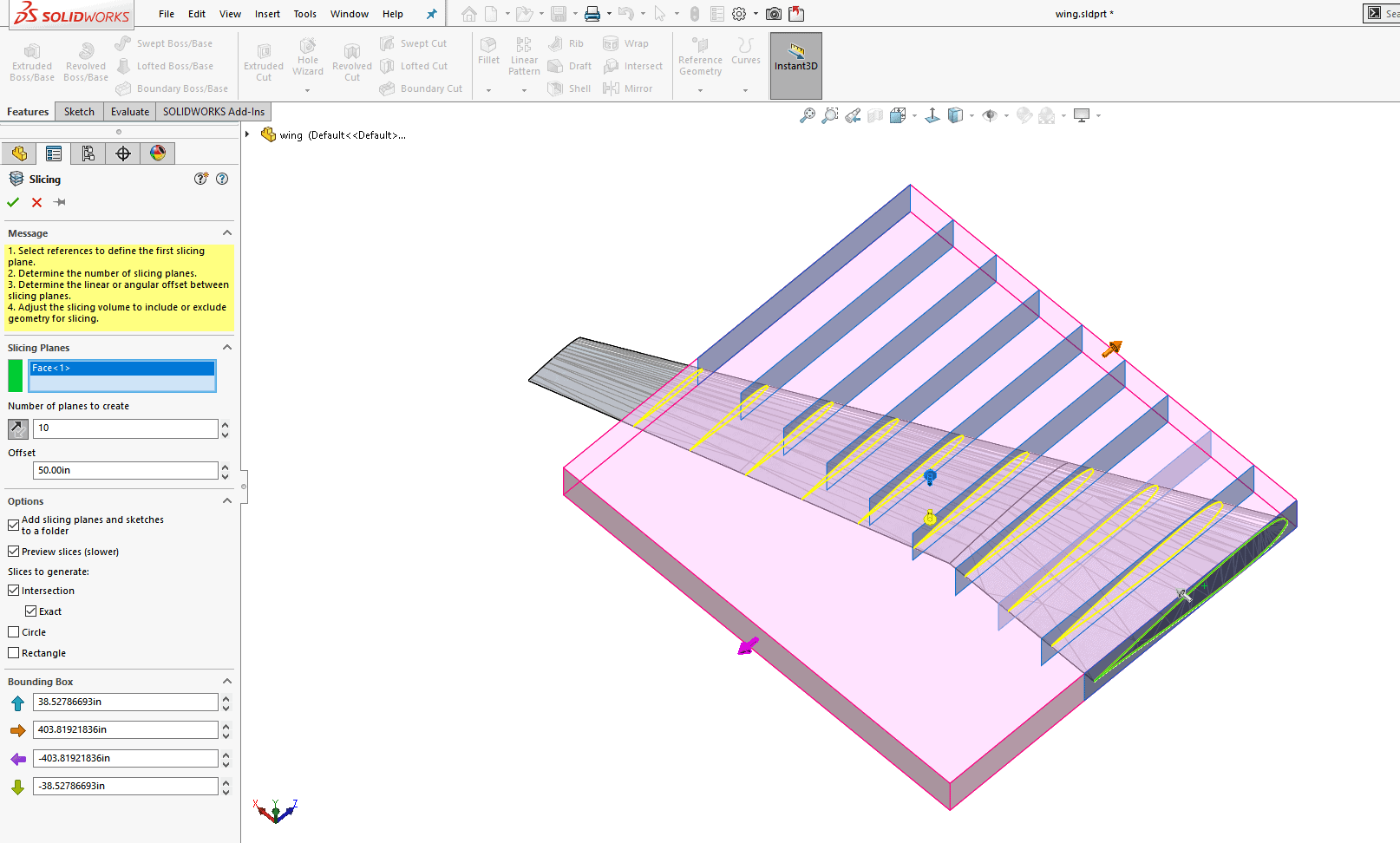
Additional Options Settings in the Property Manager for the Slicing Tool include:
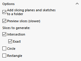
Add slicing planes and sketches to a folder; which creates a Folder in the Feature Manager that contains each individual Plane and Sketch generated by the Slicing Tool for easier organization.
Preview slices; provides capabilities to show the result before completing the command.
And under Slices to Generate:
Intersection; when used with standard BREP geometry will create an identical result to the Intersection Curve Tool, and for Mesh BREP and Graphics Bodies, will create Splines.
Exact; when checked, will create an exact intersection of the Mesh BREP and Graphics Body that results in Polylines or group of continuous line segments as opposed to Splines.
Circle; which will create a Sketch Circle centered at the intersection of the source geometry and the slicing plane, and whose diameter is the average of the length and width of the rectangle that encloses the sketch entities.
Rectangle; which creates a Sketch Rectangle that encloses the sketch entities and is also located at the intersection of the source geometry and the slicing plane.
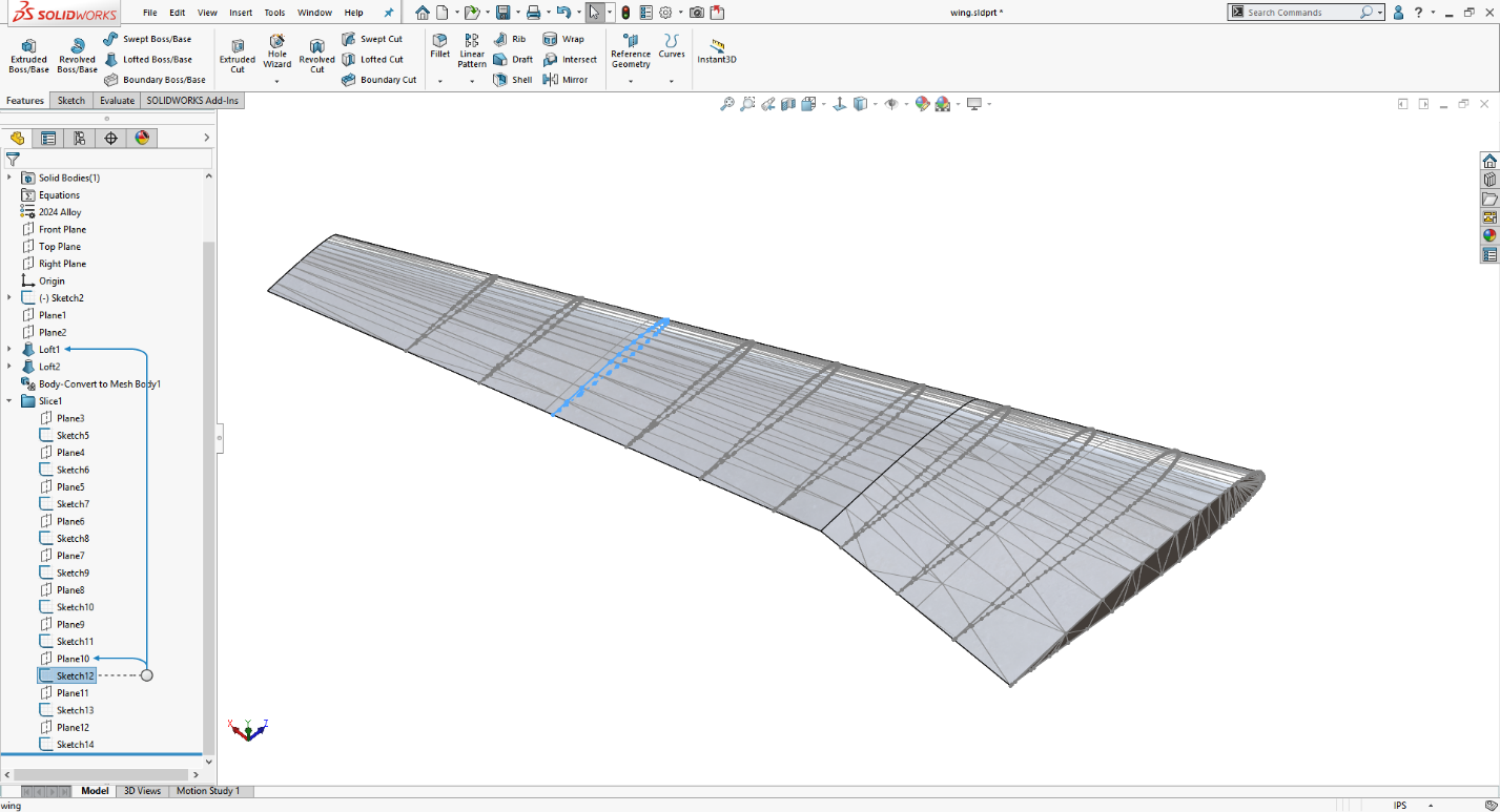
Once you are happy with your settings, selecting the OK button will generate the desired Slicing Sections. Shown below is the result of the Slicing Tool with the Folder, Intersection and Exact options checked.
I hope this part of the What’s New series gives you a better understanding of the new features and functions of SOLIDWORKS 2019. Please check back to the CATI Blog as the CATI Application Engineers will continue to break down many of the new items in SOLIDWORKS 2019. All these articles will be stored in the category of “SOLIDWORKS What’s New.”
Jordan Puentes
Application Engineer
Computer Aided Technology, LLC
Design Innovation Month – October 2018
What is DI MONTH?
CATI is declaring October Design Innovation MONTH. We’ve created a month-long series of events and activities around design innovation especially for our customers. Attend a SOLIDWORKS 2019 event, enter our rendering contest, and learn about some cool tips and tricks at the daily online events. Plan your month at www.cati.com/design-innovation-month

 Blog
Blog 