Schematic Drawing & Viewing: Two Tricks to Improving Readability
For a while now, Nodal Indicators have been an option to use in SOLIDWORKS Schematic. I initially thought they were a nice feature, but never really used them at all. In fact, most of the time in my classes that I taught or in consulting engagements I overlooked using or completely dismissed it. That all changed when I start working on a project that really had me working with my routing and connections from the schematic. I found myself flipping back and forth between schematic and 3D to troubleshoot some routing.
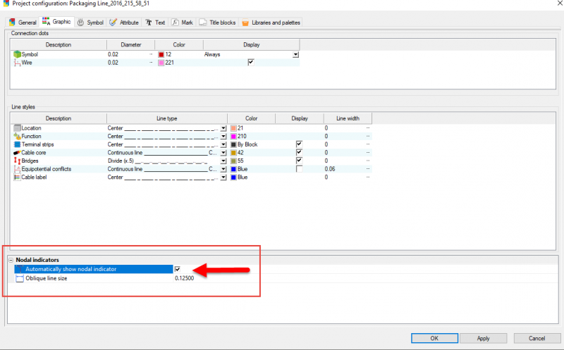
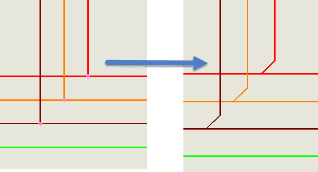
Using the “edit connection path ..” over and over had me wondering why I just didn’t break down and turn on the indicators. Once I did do that, viewing the schematic and my project became that much clearer. I have attached a couple of images of the schematic section that maybe will give you some ideas on your next project.
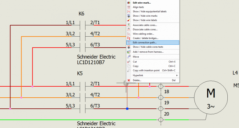
Line Widths
The other thing that helped to ease the eye strain was the line width setting in a wire style property. As you can see in the images the drawn wires line up with symbol line art quite nicely. There is some washout of the Red and Orange wires when looking at the page though and that can lead to mistakes if someone were not paying close attention.
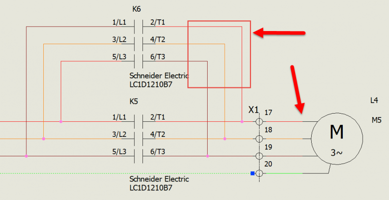
And after changing the line width:
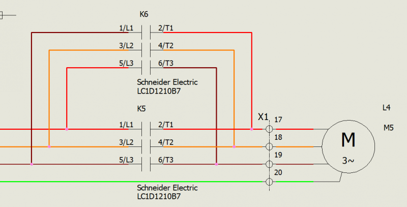
Nodal Indicators, a ‘free” symbol
As you can see, turning on the option for the indicators has given me the ability to exactly determine how my components are going to be wired together.
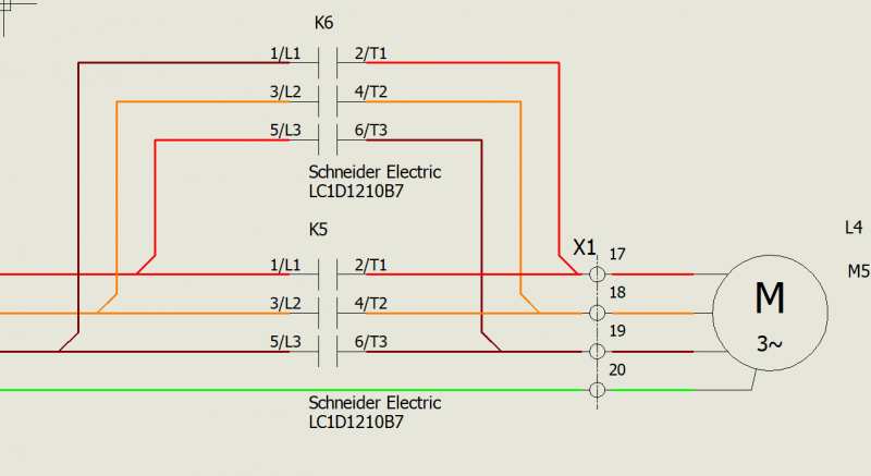
Now hopefully maybe your eyes will thank you after that long design project is done.
Corey Kubichka
CATI Electrical Product Manager
Computer Aided Technology, LLC

 Blog
Blog