Prerequisites For CATIA V6 Electrical 2D and 3D System Design
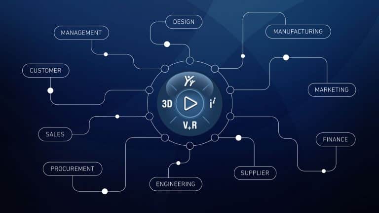
The 3DEXPERIENCE Platform is made up of a wide range of ‘Roles’ used for different disciplines and applications. CATIA V6 Electrical requires unique roles and within these roles are certain ‘Applications’ with different responsibilities when designing an electrical system.

There are two roles that everyone needs for both 2D (logical) and 3D (physical) electrical design. These are called the ‘Collaborative Business Innovator’ (IFW) and ‘Collaborative Industry Innovator’ (CSV) roles.
CATIA V6 Electrical Required Foundational Roles

Collaborative Business Innovator brings the connected environment into an entire organization. This role allows people from inside or outside of your company to securely view and share content while in a web browser. It also lets you do all of the work in a single location from design to market. You can add the power of collaboration and data sharing to your 3DEXPERIENCE platform and create a hub for your designs in a convenient place where you can collaborate on the cloud from anywhere.
On the other hand, Collaborative Industry Innovator is best described as a product data management tool. This browser-based role gives PDM additional functionality by letting users compare, markup, and view realistic CAD data. This provides a collaborative way to monitor iterations and changes to your electrical designs.
2D Electrical Schematic Role Breakdown
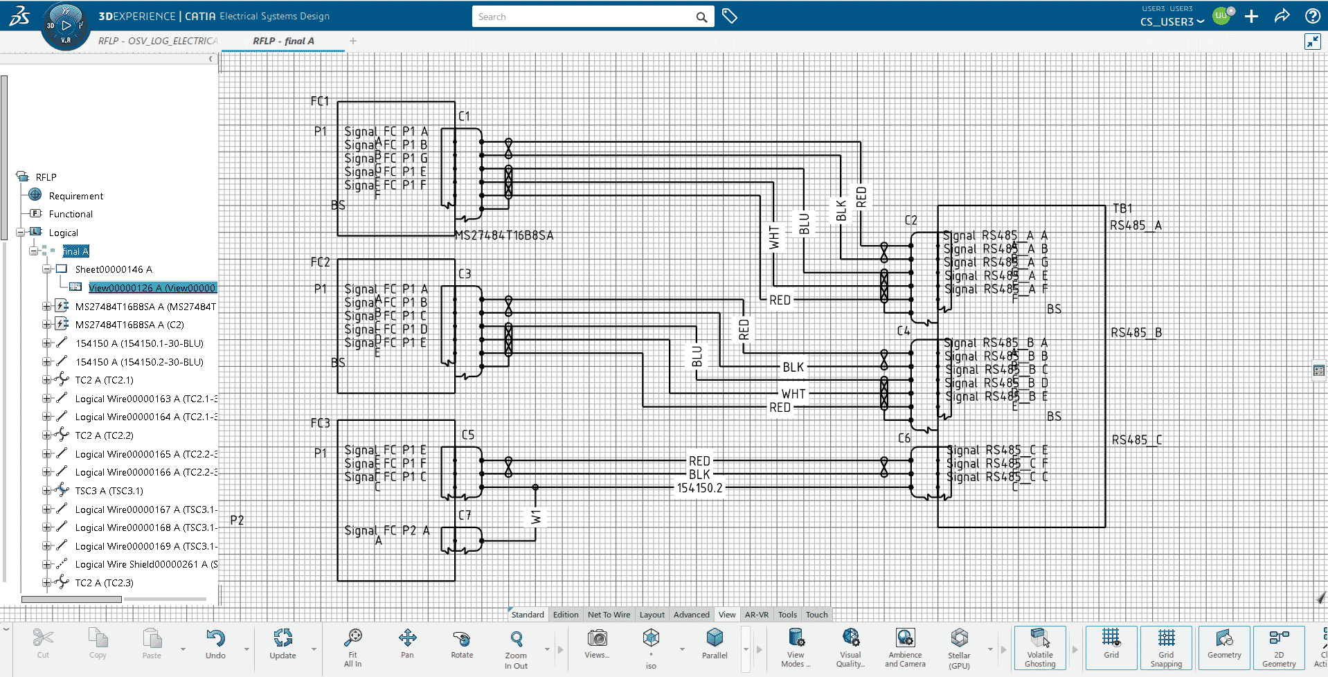
Collaborative Business Innovator and Collaborative Industry Innovator are the base roles you need for the 3DEXPERIENCE Platform. Together, these tools integrate seamlessly with the roles that make up CATIA Electrical. For the creation of schematics and 2D logical designs, you’ll need the ‘Systems Schematic Engineer’ (TIC) role. This tool allows designers to create intelligent schematics for wiring, cabling, piping/tubing, and HVAC systems. Let’s look at some of the capabilities
- Fully define 2D electrical component, port, and wire/cable libraries
- Define and connect electrical and fluid system schematics for a complete detailed logical system design
- Build logical architecture of harnesses
- Capture attributes and technology automatically within the schematic.
- Edit the attributes of electrical components within the schematic
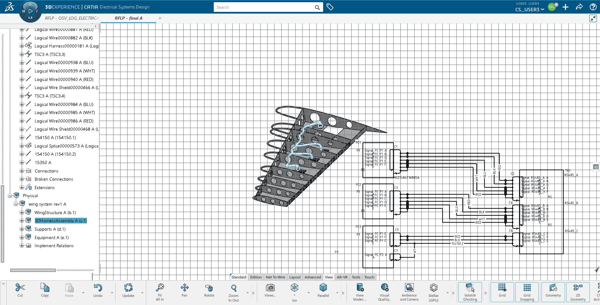
- Create links between logical components and realistic 3D representations
- Analyze connectivity and quality of schematic design and ensure synchronization with the 3D design using business intelligence rules.

3D Physical Electrical Design Role Breakdown
For 3D physical design, you’ll use the ‘Electrical 3D System Designer’ (ELG) role. This tool is an integrated 3D electrical development environment, which enables the physical design of wire harnesses and cabling in the conditions of the complete product. Some of the main features to point out include:
- Create electrical geometries, electrical branch geometries, and electrical physical systems
- Synchronize electrical schematics to 3D designs to improve electrical systems quality and consistency
- Create or import conductor specifications
- Design and optimize electrical wire harness bundles and cable ways accurately in the realistic environment of the full system
- Route 3D wires and cables to obtain exact bundle diameters and wire/cable lengths
- Simulate routes between selected network ends and compute route lengths

CATIA V6 Electrical provides a logical to physical electrical system design solution and is fully integrated with the 3DEXPERIENCE Platform. This means that you can easily incorporate CATIA V6 Electrical into your design lifecycle process. This allows you to efficiently collaborate with the other roles that 3DEXPERIENCE has to offer, giving you a more seamless process.
Jacob Quintana
Application Engineer Specialist, Electrical
Computer Aided Technology

 Blog
Blog