Nominal Wall Thickness Inside Plastics Simulation
Wall Thickness – a major concern when designing a plastic part.
During the injection of the mold the melted plastic flow front will always move in the direction of least resistance. You can think of this similar to water flowing through a pipe. The larger the pipe the easier the volume of water will flow. If the wall is too thick in comparison to other sections of the part the plastic flow will “Race Track” or move ahead of the rest of the flow front. This causes issues such as air traps, weld/knit lines, and possible cosmetic problems. If the walls are too thin this can cause issues such as “Short Shot”. Short shots occur when the flow front becomes to hard to push by the machine (typically reaching the maximum injection pressure), or the flow front cools too fast due to the lack of volume. Short shots do not fully fill the cavity and create an incomplete plastic part. Ideally a part will have a uniform wall thickness. In real life this is hard to accomplish but being able to predict areas that may be a problem before running an injection analysis helps an engineer find a good balance.
SolidWorks has always had the ability to check the thickness of a part through the evaluate tab of the command manager. The command is “Thickness Analysis” and it has been the go to command to determine different thickness within a part.
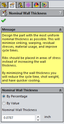
Nominal Wall Thickness Command
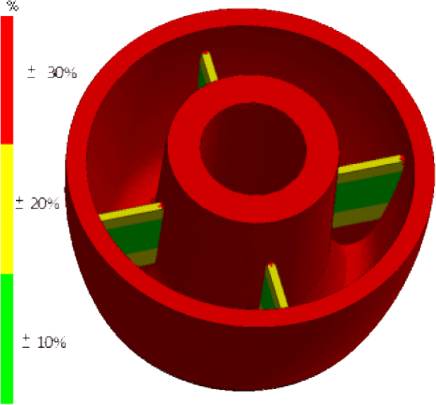
Now SOLIDWORKS offers a “Nominal Wall Thickness” tool under the Advisor category of the Plastics Tree. The “Nominal Wall Thickness” command allows a user to compare thickness in the model based on a value or percentage. This addition gives the user a quick thickness analysis right inside the Plastics Interface.
The results are a quick and easy to understand plot that facilitates the reduction in sink, short shot, and warping.
Have you used this command before? want to learn about a different command in SOLIDWORKS? Let me know in the comment section below!

 Blog
Blog 


