Partake in Partitions: Meshing in 3DEXPERIENCE Simulation
The 3DEXPERIENCE Platform has drastically changed the way that CAD data is created, reviewed, stored, and validated. As a SOLIDWORKS Simulation user for many years, it has added a lot of great tools to make advanced simulation studies more robust and more accessible than ever. Arguably one of the biggest advantages of meshing in 3DEXPERIENCE Simulation is the ability to use advanced mesh types like hexahedrons, wedges, quad shell elements, etc. Advanced elements like hexahedrons (also known as brick elements) offer more accurate results given similar mesh density to traditional tetrahedral elements. You can see a tetrahedron (top) and a hexahedron (bottom) in the figure below.
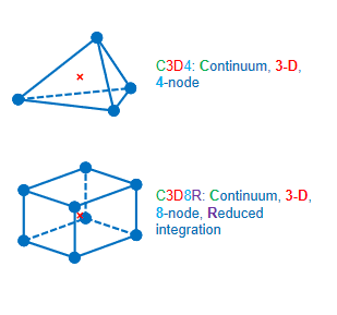
Figure 1. Image courtesy of Dassault Systemes.
One of the downsides of hexahedral elements is the meshed geometry must be such that there is a sweepable shape. This means that overhangs, extra extrusions, and holes that don’t follow the sweep direction would all make it impossible to use these advanced elements for analysis. Many simulation programs get around this by splitting or “partitioning” the shape into separate volumes that are sweepable. As usual, 3DEXPERIENCE Simulation does this as well but ups the ante above those other tools. Let’s take a look at partitioning for simulation on the 3DEXPERIENCE Platform.
Partitioning for Better Meshing
We’ll start with the part below. It is a cylinder from an air-cooled motorcycle engine. Notice the removal of small features like fillets on the simplified version in the figure below.
Figure 2
We can take the simplified model into the Structural Model Creation app to get feedback on how to best mesh this shape. Select the compass, click Structural Model Creation, click “Partition Hex Mesh,” and finally select the component itself as a support. 3DEXPERIENCE Simulation will then color the part according to the methods that can be used to mesh it.
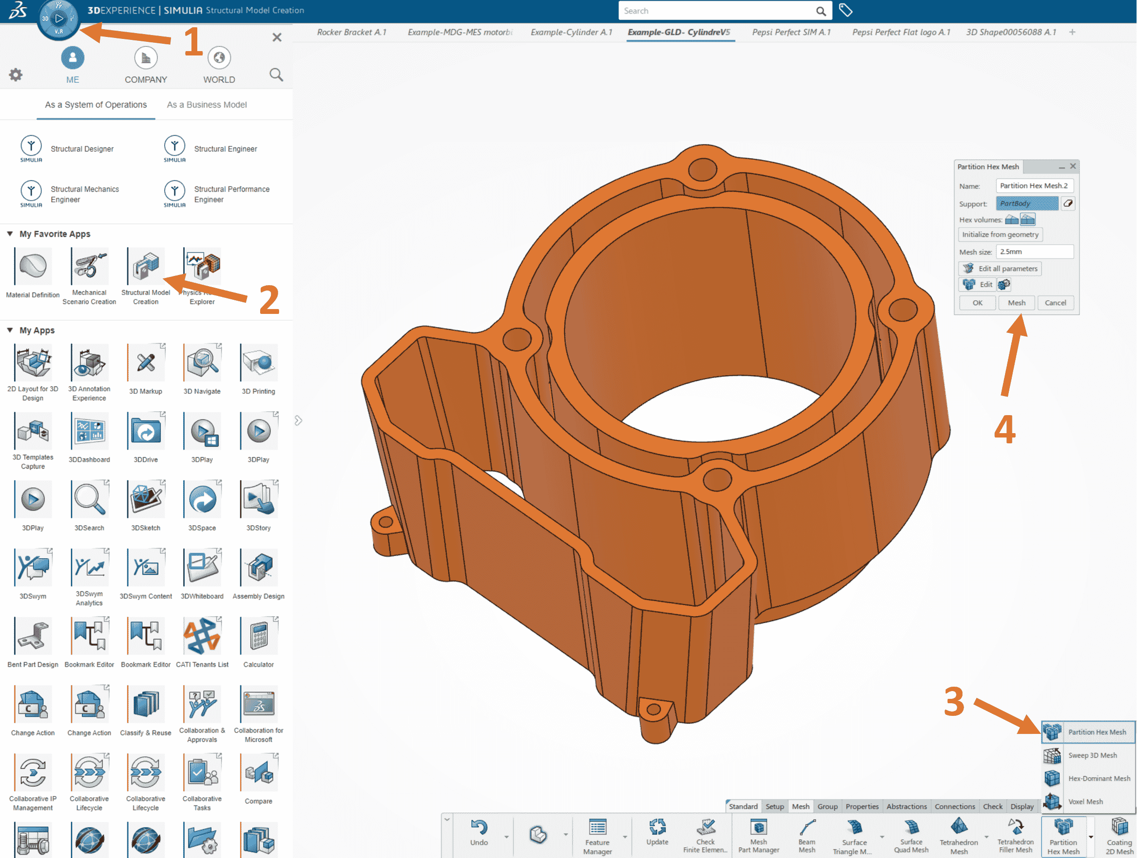
Figure 3
The orange color on the part in the figure above indicates a volume that is NOT mesh-able by hexahedral elements. As is, 3DEXPERIENCE Simulation will assign a tetrahedral mesh instead. However, many of the areas on this model could be split from the others into sweepable shapes. This is where partitioning comes in!
Meshing in 3DEXPERIENCE with the Partition Tool
The partitioning tool is most easily accessed via the Simulation Model Preparation app included with your 3DEXPERIENCE Simulation role. Simply click the compass and select the app from the list to launch it. This app contains sets of tools used for simplification of CAD models for use in simulation. We’re looking for “Partition” under the “Idealize” tab. See figure 4 below:
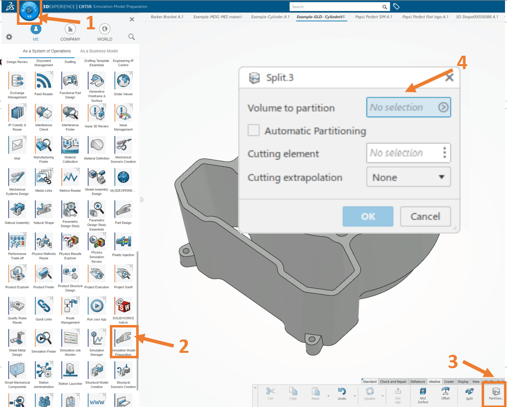
Figure 4
All we must do to partition the component is to select the part as the “Volume to partition” and use cutting elements such as faces, planes, surfaces, etc. to divide the part into sweepable features. For example, if I want to partition one of the assembly tabs, I can select the face that it is extruded from as a cutting element. If we extrapolate that face infinitely, it will cut through the tab, separating it as its own volume. See below:
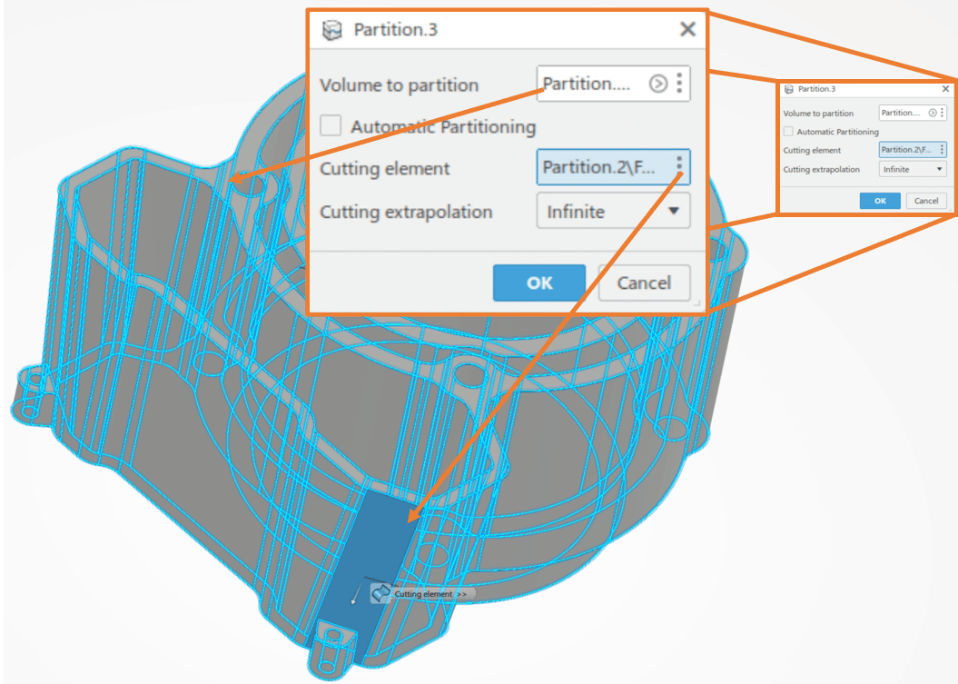
Figure 5
Now if we check the color coding to view the types of mesh we can use for each volume, we see the small extrude we split off is colored yellow-indicating a hex-meshable volume. See below:
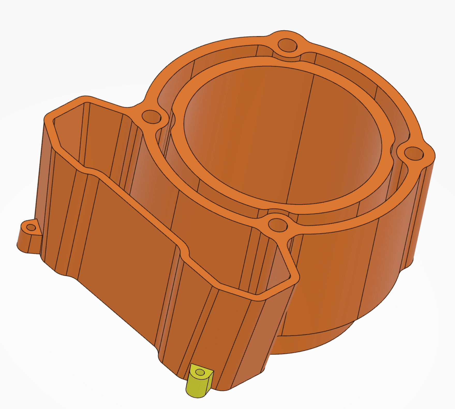
Figure 6
Automatic Partitioning for Automatic Meshing
We can continue splitting features manually to create the fully partitioned model. It’s a simple process that works very well. However, recently one of the updates to the meshing feature in 3DEXPERIENCE Simulation has added an automatic partitioning tool to do all of that work for you! All you must do is select the volume, and click the checkbox for “Automatic Partitioning,” and soon you will have a fully hex-meshable part! You can see my example below:
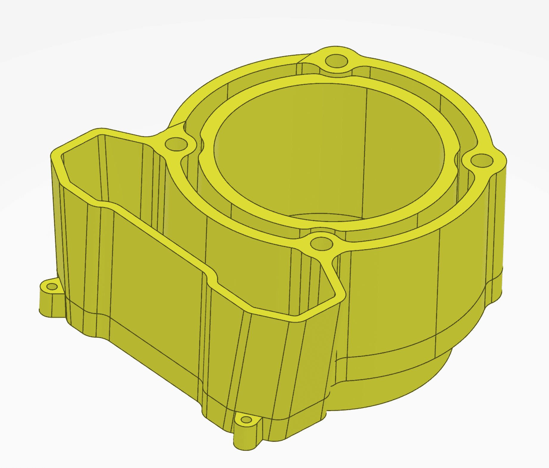
Figure 7
As with all automated tools this will not work for every geometry, but in my experience, it does a great job splitting prismatic parts like this one. A further benefit of using the “Partition” tool is that the partitioned hex-mesh will be fully conforming. That means that adjacent volumes of hex meshes will share common nodes at the volume’s boundary.
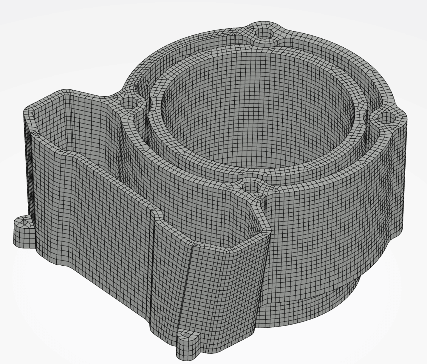
Figure 8
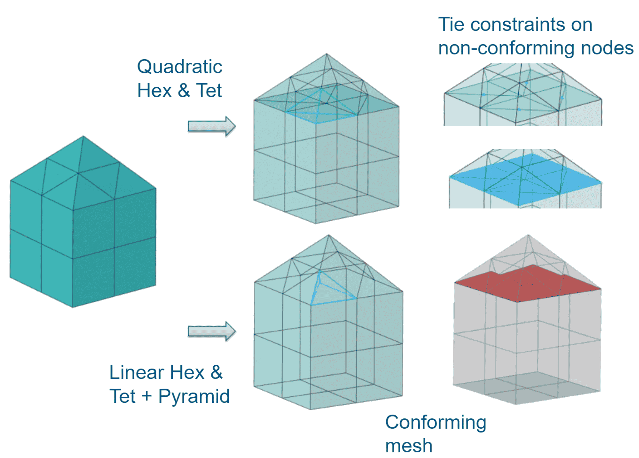
Figure 9. Image courtesy of Dassault Systemes.
Finally, if you are attempting to mesh a part that has non-sweepable volumes, the partition hex-mesh algorithm will assign tetrahedral elements to the non-hex volumes and create a “tie contact” between the volumes automatically! Optionally, you can also specify a layer of pyramid elements to act as a conforming mesh boundary between the hexahedral elements and the tetrahedral elements. You can see a visual representation of how that works below:
Thank you for partitioning some of your time to read my blog today. Simulation model preparation is a vital step in achieving accurate simulations, and again the 3DEXPEREICNE Platform goes above and beyond in enabling engineers to do what they do best.

Matt Sherak
Sr. Simulation Product Specialist
Elite Application Engineer
Computer Aided Technology

 Blog
Blog