Designing Custom Packaging (Part 2)
If you remember from my last article Designing Custom Packaging (Part 1) I had left off after modeling the components and the containers. Then I created assemblies representing the tightest possible arrangement of the computer lab within the containers, allowing for one inch of spacing for the more delicate components.
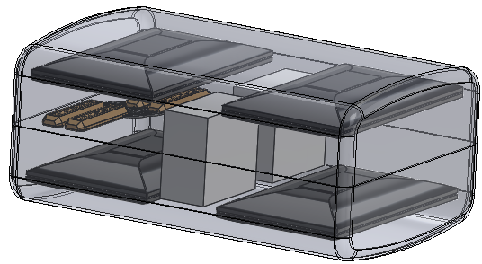
Clam Shell
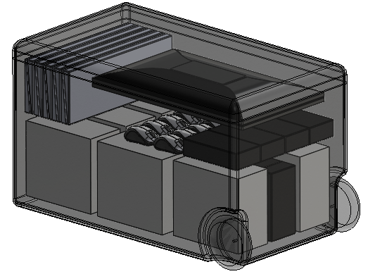
Rolling Crate
To create the negative space for the Rolling crate I began with the model of the crate (shown here in cross-section)
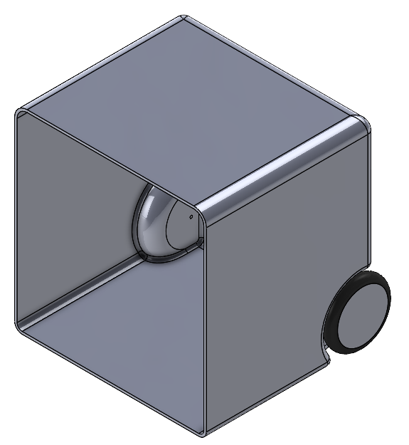
Notice here that the crate is still a single unit with the lid attached.
I used the Intersect command to create separate bodies of the lid and the internal volumes of the lid and crate.
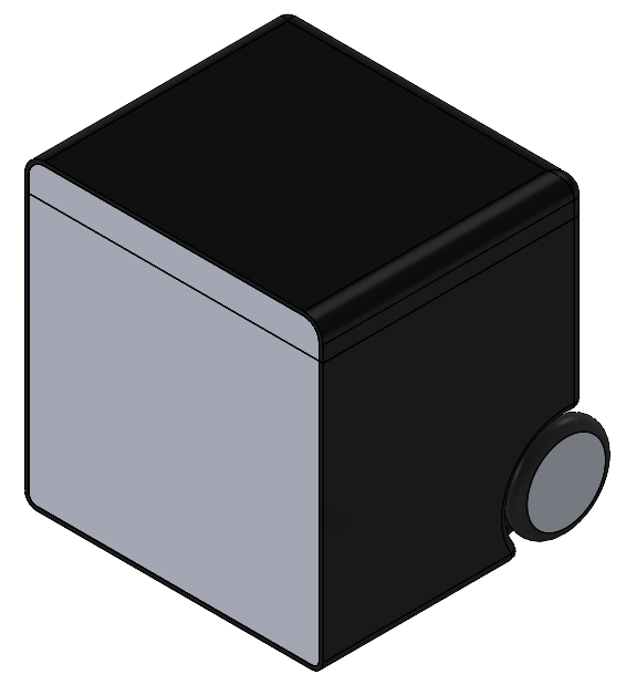
(Shown here in cross-section view with the crate and lid made black)
So, here is the negative volume. Next, I used the Save Bodies command to create new parts from the internal volume called CPU cavity and Lid Cavity.
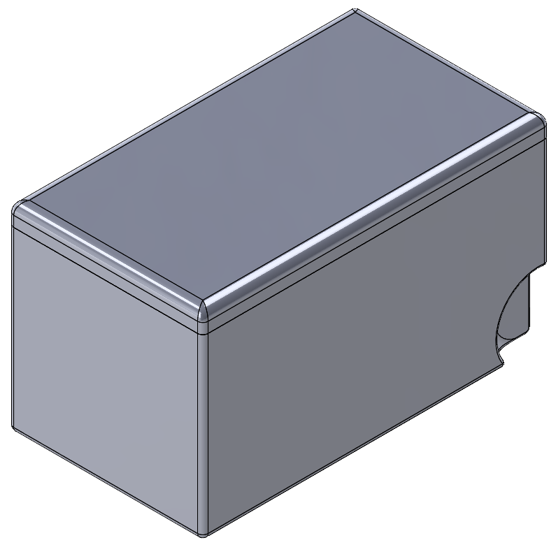
These new parts were inserted into the assembly with the Crate and components. I then removed all the spaces taken up by the components. This was done by editing CPU cavity model and using the Cavity command to subtract the volumes of the components from the internal volume (Shown here transparent and with components in cross-section).
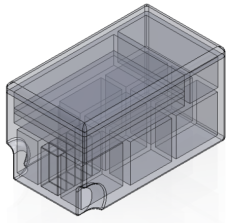
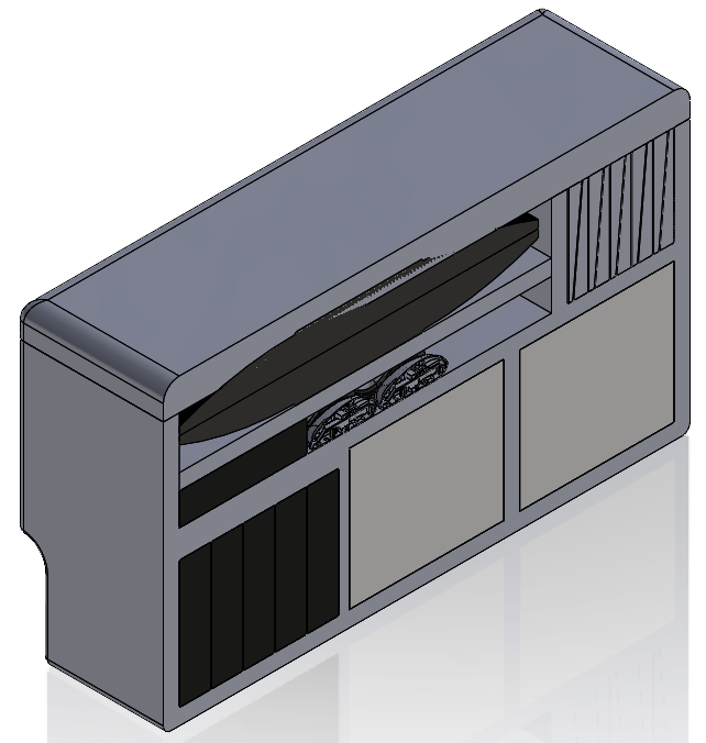
This same process was followed with the Clam Shell case (Shown here transparent and with components in cross-section).
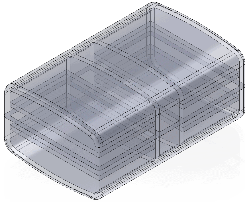
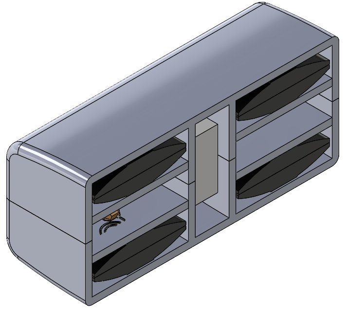
By adding simple Cuts and Bosses I squared off the internal volumes to create rectangular spaces for the components while leaving 1/8” interferences to hold items tight.
The process I used to document and create the one-inch thick foam pieces that were cut to fit into the Clam Shell and Rolling Crate will be detailed in the next blog article of this series, so stay tuned.
Dennis Barnes
Applications Engineer, SOLIDWORKS Technical Support
Computer Aided Technology, LLC

 Blog
Blog