Clearly Communicate Configuration Differences in SOLIDWORKS BOMs
Configurations in SOLIDWORKS are a great way to represent variations of a design in a single document. We can have Part configurations that change features, dimensions, materials, and custom properties. We can have Assembly configurations that change components, assembly features, dimensions, configuration-specific custom properties, or simplified versions.
For our top-level assembly BOMs, we can select additional configurations to show the Quantity for each component per configuration.
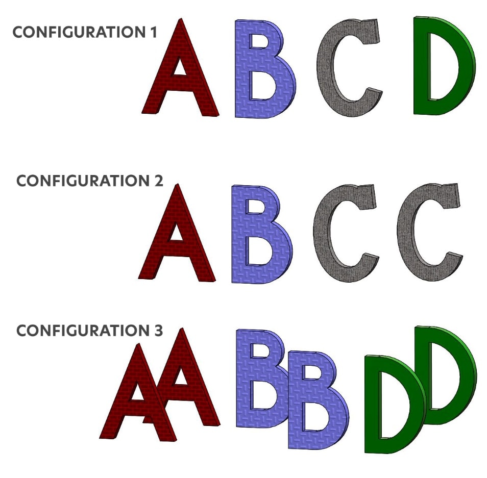
For example, our Test Assembly has 3 configurations, named Configuration1, Configuration2 and Configuration3.
Configuration 1 has components A, B, C and D
Configuration 2 has components A, B and (2) C components
Configuration 3 has (2) A components, (2) B Components and (2) D Components.
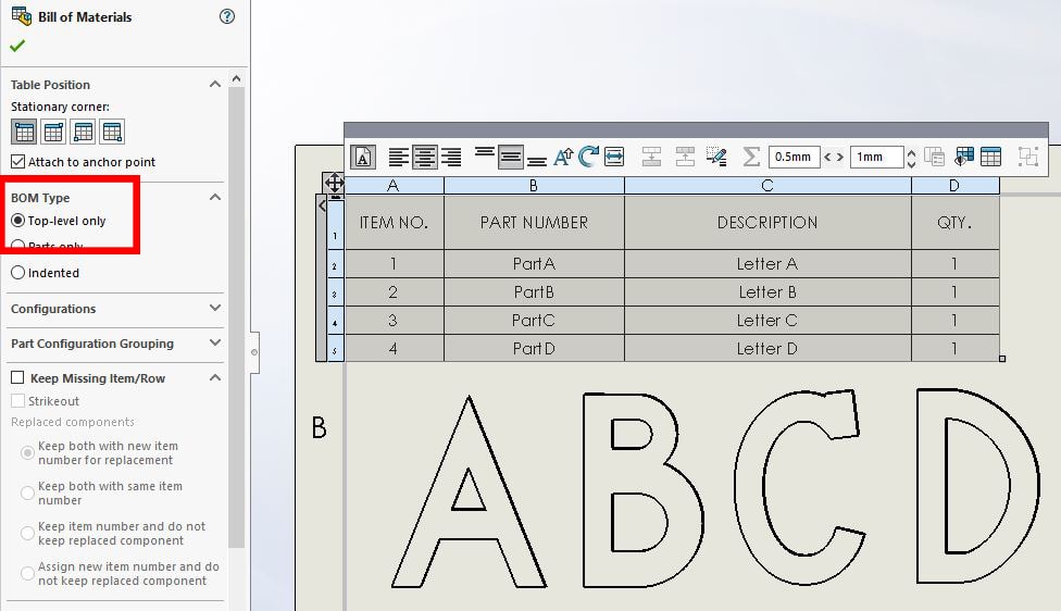
Lets jump to our drawing and create a Bill of Material using Configuration1.
To show additional configurations in the BOM, the BOM must be a Top Level BOM type.
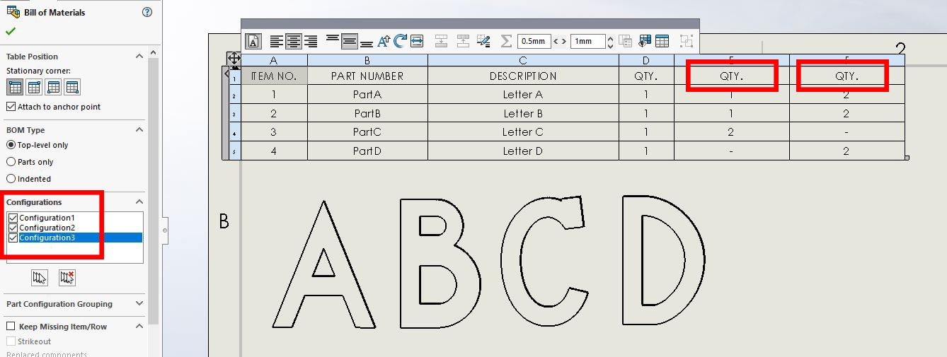
To add a QTY column for the other configurations, expand the Configuration field and select which Configurations to include in the BOM. The Bill of Materials fills in with the quantity of each component per configuration.
We need to add the Configuration name to each of the QTY columns. Right click on any of the QTY cells and select ‘Show all configurations’.
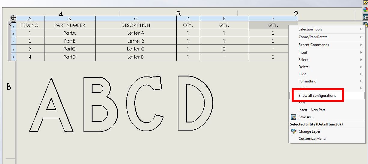
The column headers now show the Configuration name and QTY.
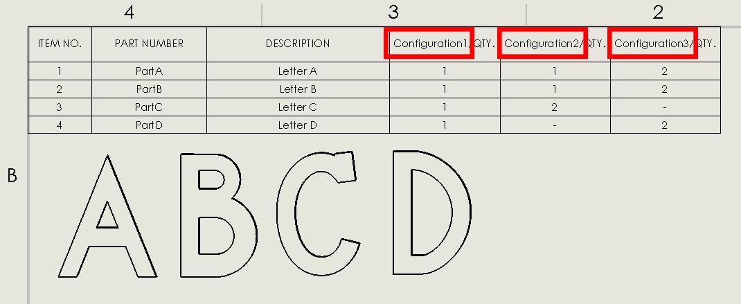
This BOM clearly communicates the differences between configurations in your design.
Laura Nickerson, CSWE
Application Engineer
Computer Aided Technology

 Blog
Blog