Automatic Circuit Arrows in SOLIDWORKS Electrical
Origin and destination arrows in SOLIDWORKS Electrical let you create a continuity link between wires in different schematic drawings, or in the same drawing if required. It could also be for cables in line diagrams or wires in schematics. Placing these can be done automatically, saving yourself a couple of steps.
This command is used to automatically generate the origin-destinations between wires with the same number. A specific symbol is placed at the end of the wire and a configurable text label is placed. That label can be driven with a formula from the project configuration setup.

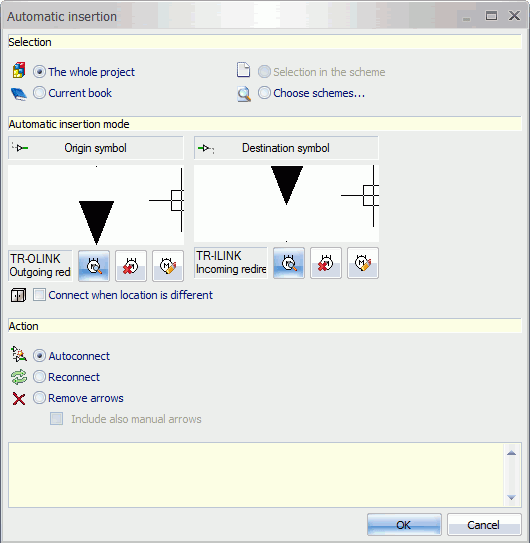
A dialog box prompts you to enter the options.

For Selection:
- The whole project: Treats all the drawings in the project.
- Current book: Treats the drawings in the book to which the current drawing belongs.
- Selection in the scheme: Treats the selected wires.
- Choose schemes: Opens the drawings selector allowing you to select the drawings you wish to process.
Following the Selection area is the Automatic insertion mode. This is used to select or change the symbols representing incoming and outgoing origin/destination symbols.
 Opens the symbols selector to select the desired symbol.
 Used to detach the symbol.
 Opens the symbols editor in order to modify it.
Action
- Autoconnect: Generate origin-destinations automatically.
- Reconnect: Update the existing origin-destinations according to the operations performed in the scheme.
- Remove arrows: Removes all the origin-destination arrows for the selection. The “Include also manual arrows” option allows you to process manual origin-destination arrows too.
Optional:
Connect when location is different: When this option is selected, it allows you to activate the connection between 2 wires in different locations as well.

 Blog
Blog