Reverse Engineering for the Pros
CREAFORM has released a new scanner; the Go!SCAN Spark! You can read more about the new features here: Go!SCAN Spark. One of the new features of the Spark is the ability to scan at an impressive rate of 1.5 million measurements/ sec with an adjustable scanning area which makes it perfect for reverse engineering. In this blog, I would like to cover a scanning application with the new Goscan Spark.
Here we have a scan of a custom finished golf wedge.
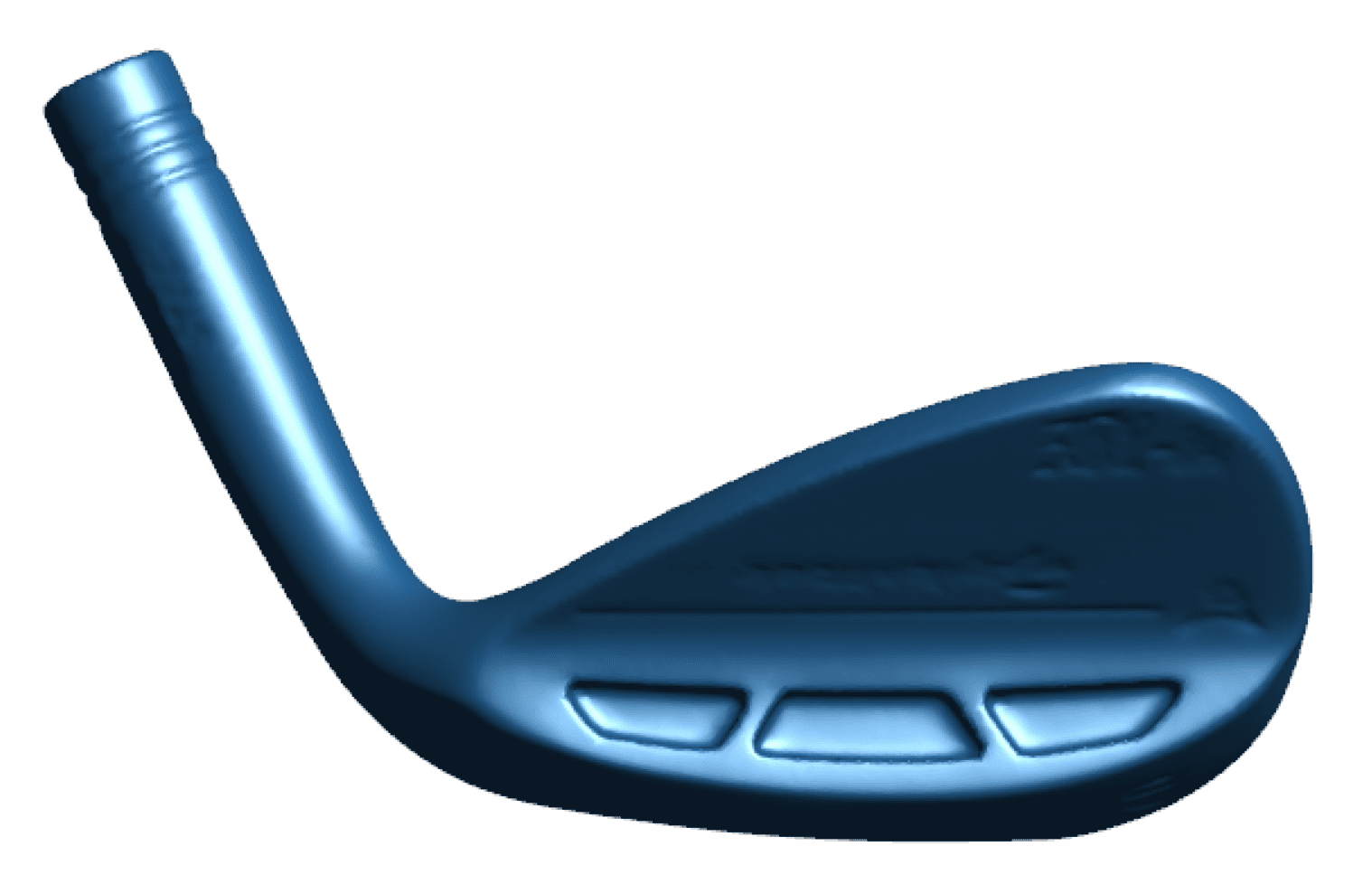
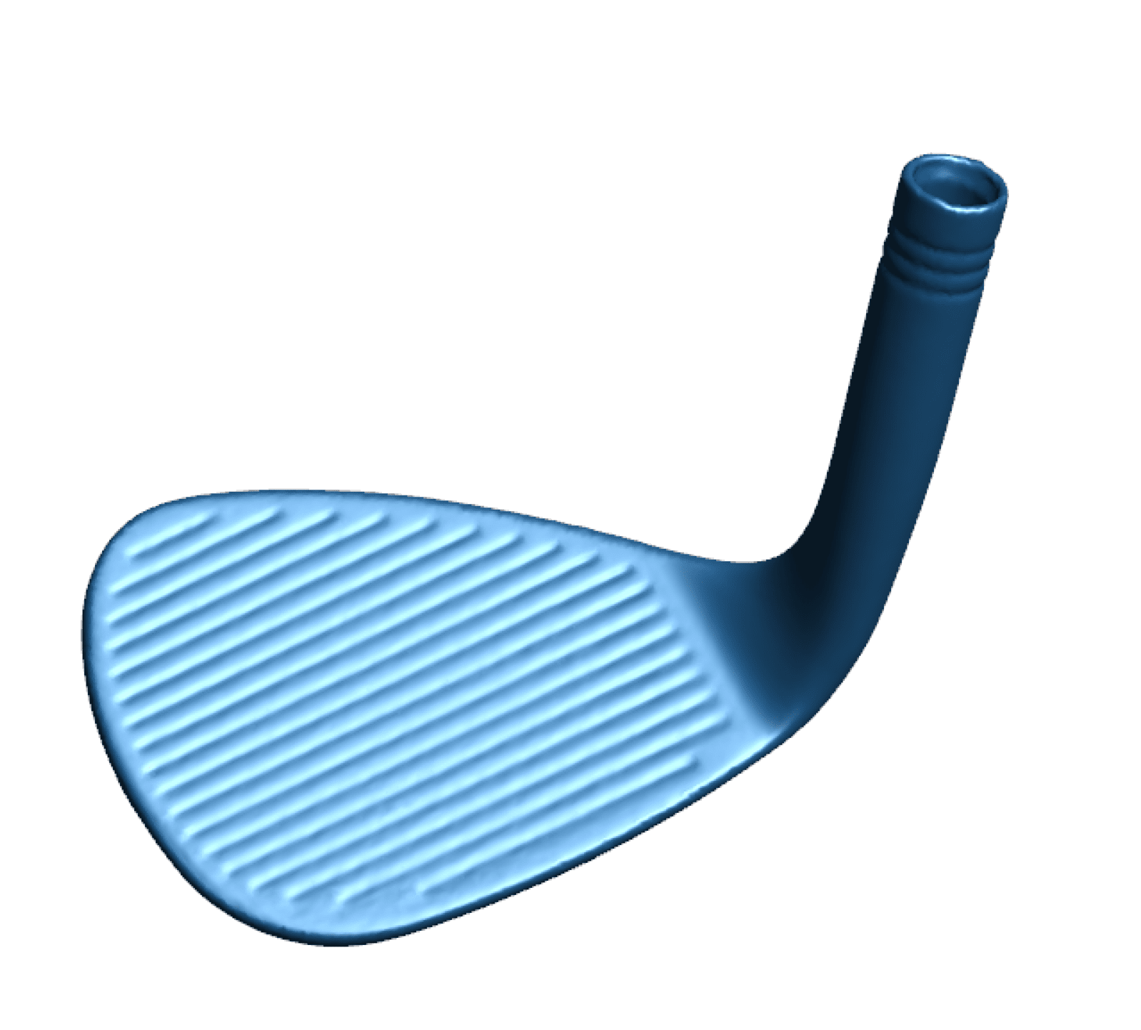
Creating this wedge in CAD software may seem simple but could quickly become complex giving the unique geometry. In fact, there is a lesson that CATI covers during SOLIDWORKS advanced part modeling that discusses using Loft and Boundary features with start and end constraints to model this wedge from scratch. But since this wedge has a custom profile made special for the user, we will need to use a 3D scanner to reverse engineer it.
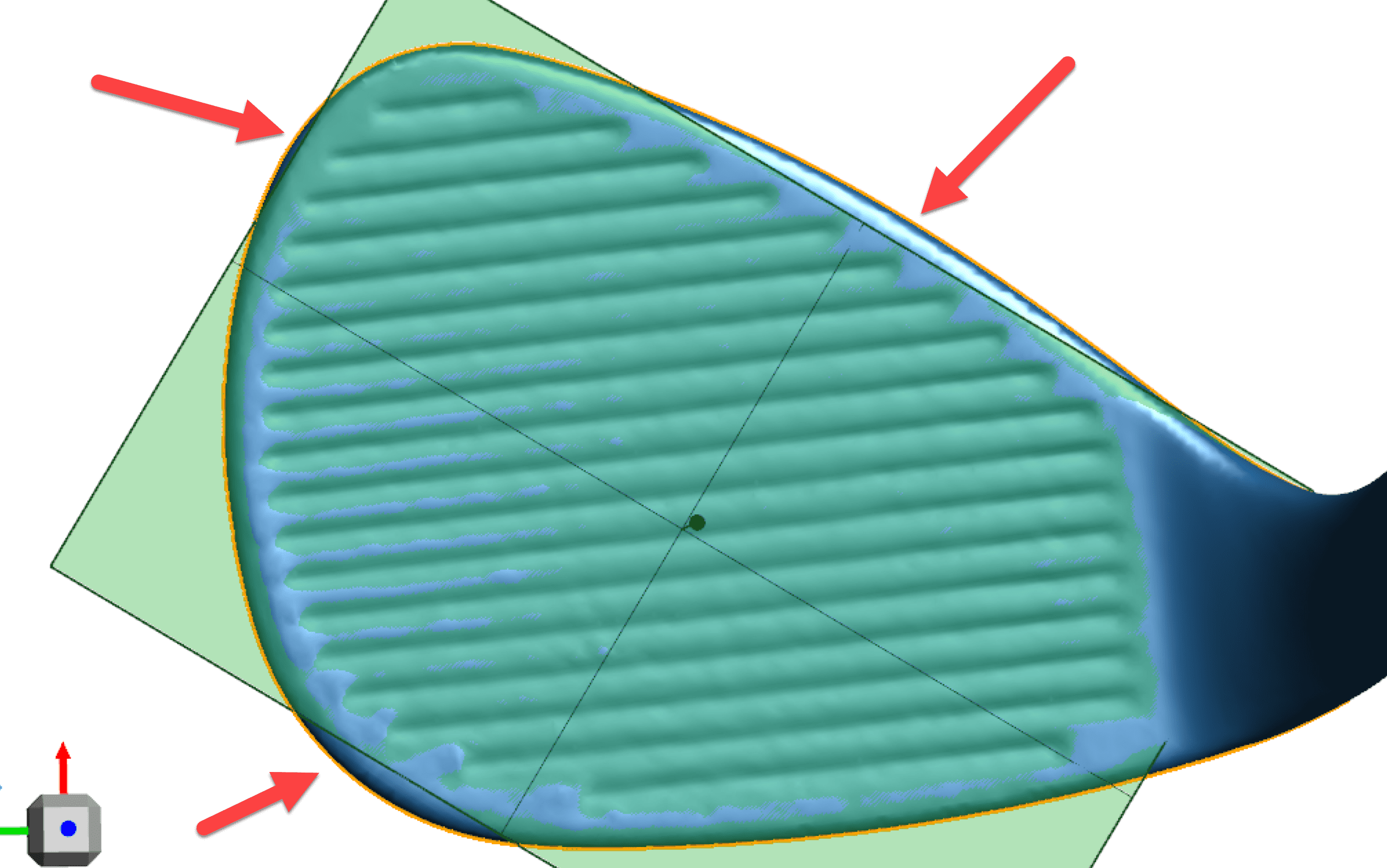
The first step in the process is to extract the silhouette and cross-section of the face for a 2D sketch.
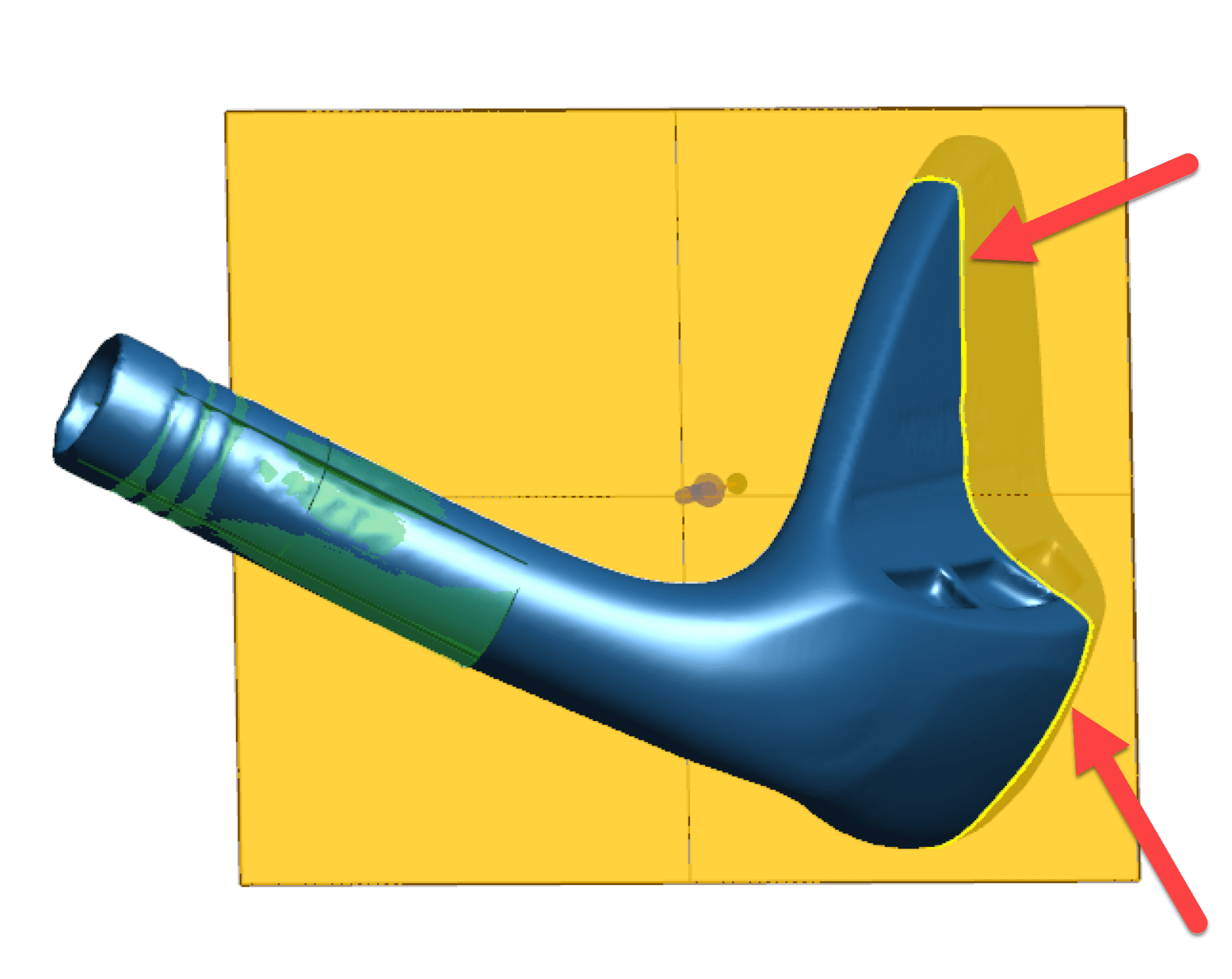
The second step would be to extract a cylinder from the shaft.

The next 2 steps will take place in Solidworks which are a simple extrude and cut. So we first need to send the information from Vxmodel to Solidworks.
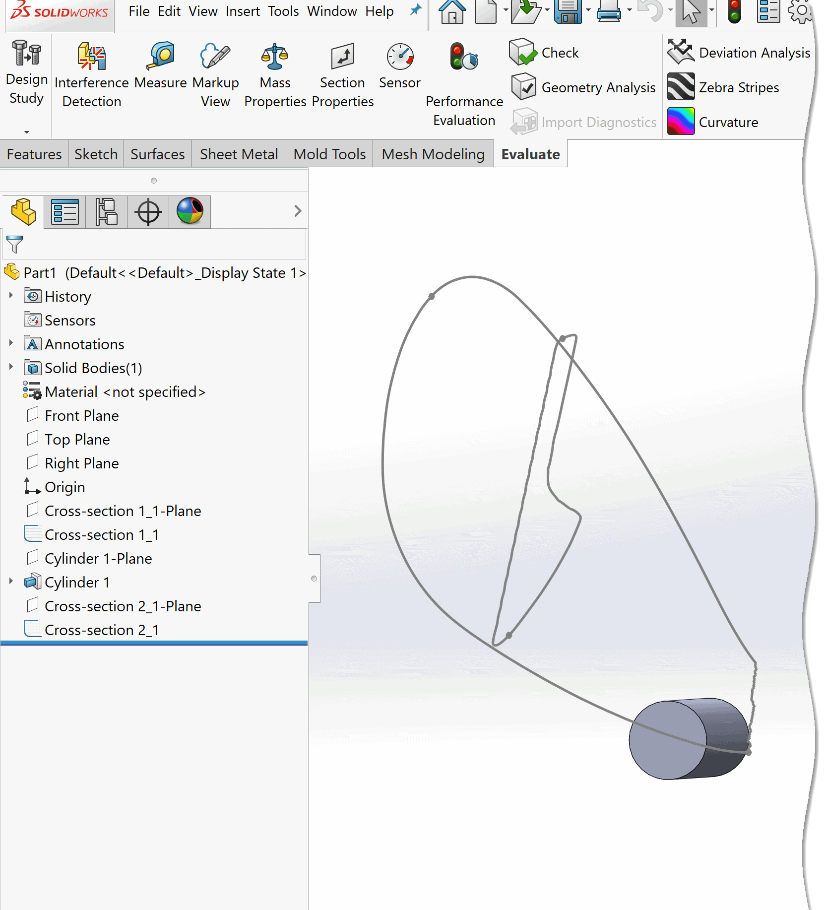
Now that our Silhouette, Cross-section and Cylinder are in Solidworks we will proceed to make an extrude and cut.
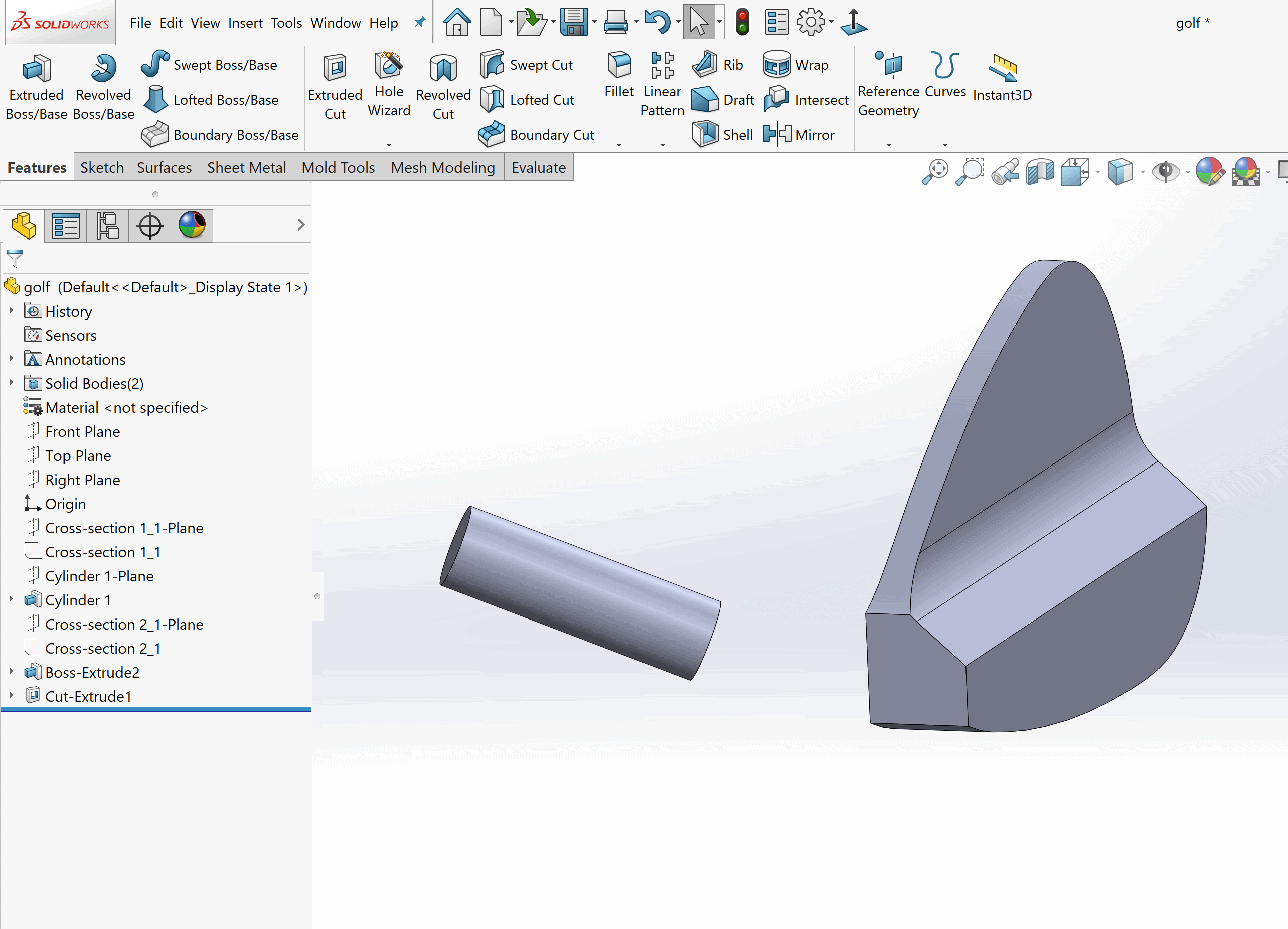
There are only a few steps left and the next one is critical for the customization of the Wedge. We will need to extract a curved surface from the Wedge using Vxmodel surfacing tools.
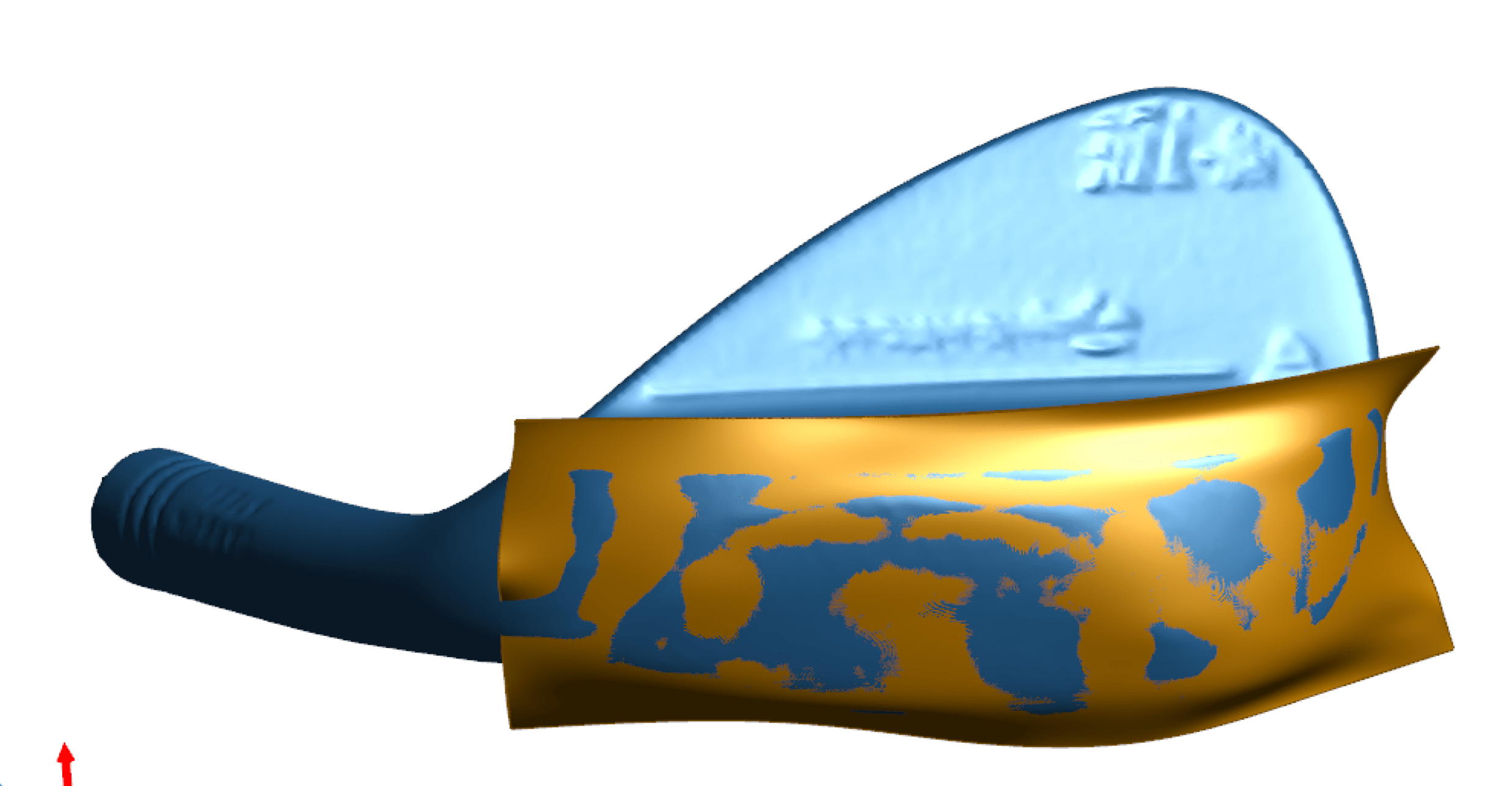
This unique tool creates a surface that follows the contour of the machined profile to match it at a high degree of accuracy.
Finally, with in about 30 minutes, we have a finished CAD model for production.
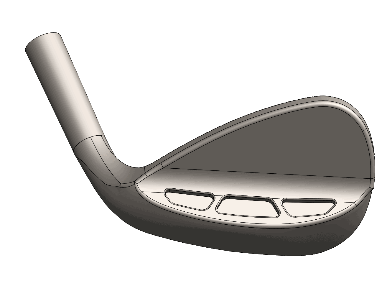
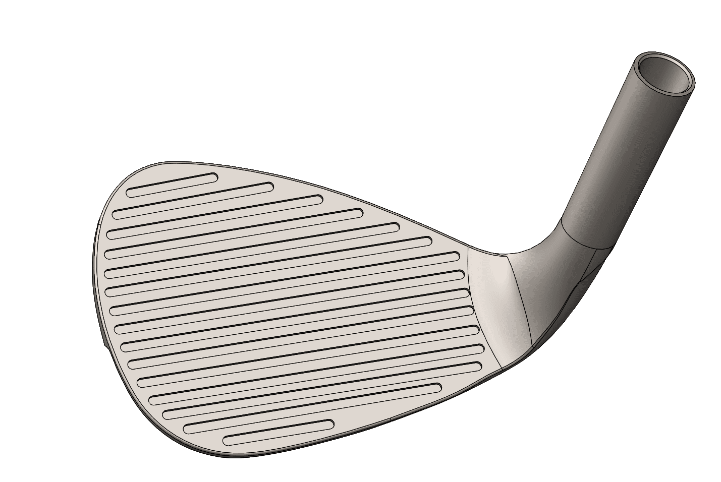
For more information on 3D scanning visit our 3D scanning blog section at CATI.com.
The engineer’s first problem in any design situation is to discover what the problem really is.
Bob Renella
Product Manager
Computer Aided Technology, LLC

 Blog
Blog