SOLIDWORKS Flow Simulation: Joule Heating
SOLIDWORKS Flow simulation is a fantastic tool for simulating internal or external fluid flows. It also features very robust conjugate heat transfer capabilities; including conduction, convection, and radiation. The combination of these capabilities has made SOLIDWORKS Flow Simulation the go-to program to simulate cooling electronic components. It does this fantastically right out of the box, but with the addition of the Electronics Cooling Module, it gets even better! Today I’d like to cover one of the flagship capabilities of the electronics cooling module; Joule Heating.
Joule heating adds the ability to run power through electronic components. Using the geometry and electrical resistance of those components, Flow Simulation will calculate the heat generated by those parts. As with all blogs, the best way to communicate the feature is to show it!
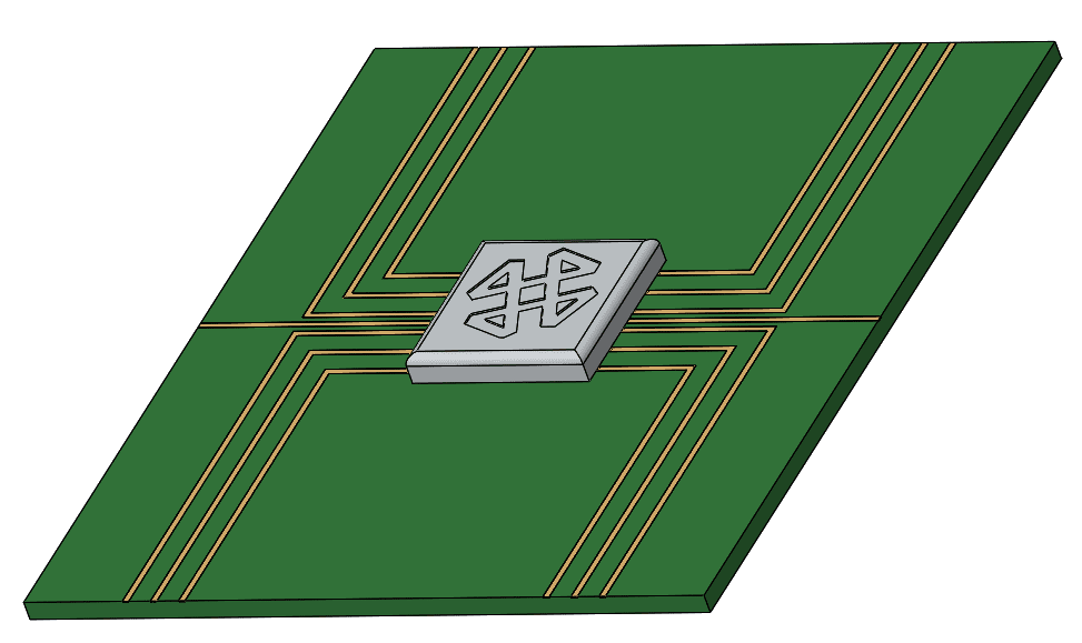
See below a simple chip and PCB assembly, with some printed circuit busses on them. For now, we will treat this study as an external analysis with standard ambient temperatures and pressures.
With “Electrical Conditions” added to the flow study tree, add the electrical conditions to the model to match the real-world conditions.
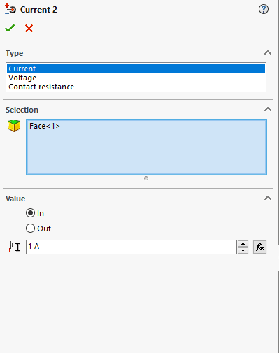
Note from the electrical conditions shown above that there are options for current, voltage and contact resistance. Contact resistance is an option for transferring electrical energy through contacts between components. This is useful for simulation of electrical terminals and junctions and is not covered in this blog.
For this model, I have added a simple current in-out approach to each individual conductor run. (NOTE: When using a current in and out combination, the current in value must be identical to the current out value)
Officially supported electrical combinations include:
- Applying a voltage drop over the length of a conductor (i.e. 5 V at one end 0.1 V at the other)
- A current and a voltage (i.e. 0.1 Amp at one end and .1 Volts at the other)
I have left the heat generation of the central chip out of the analysis as it gets much hotter than the individual lines going into it, making it difficult to see the heat the lines generate. I have also increased the typical amperage through a PCB bus to 1 Amp so that the heating is more obvious.
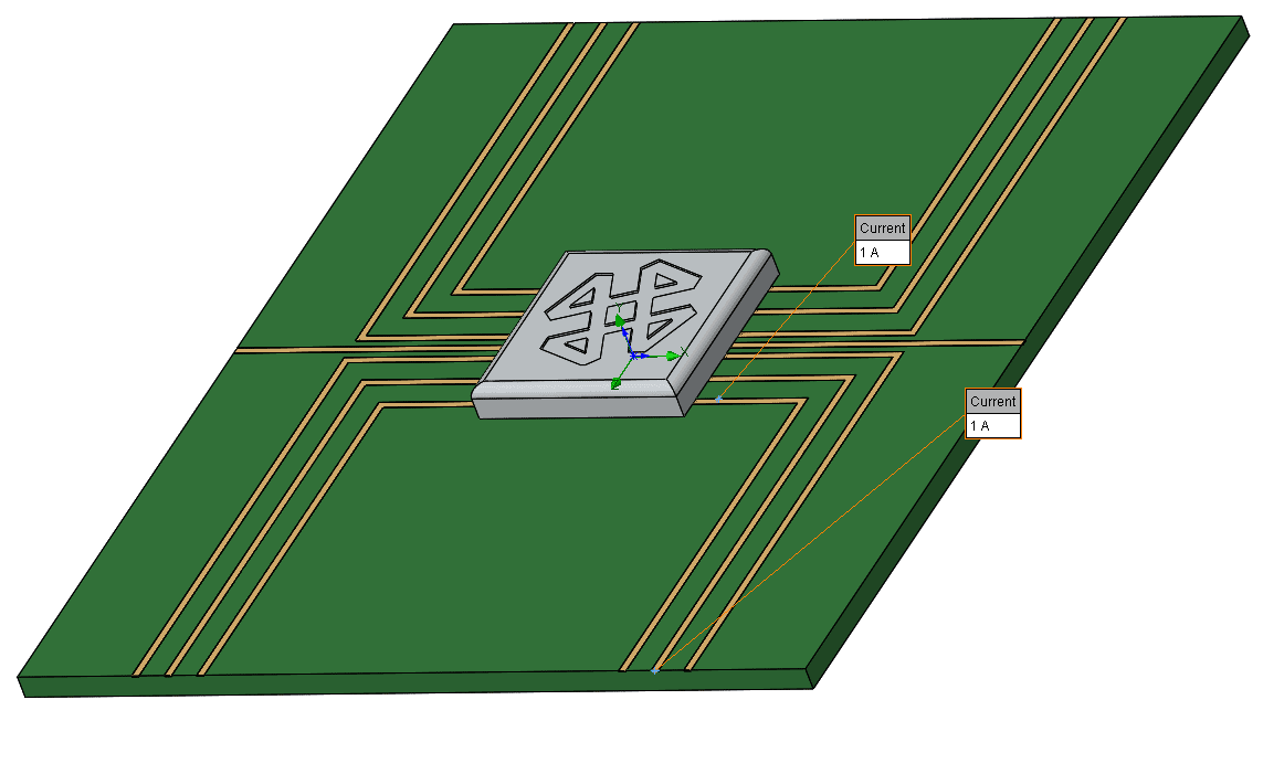
A face has been selected on each end of the single electrical bus to define the current in face and current out face.
Below are the results from the heat generation of just the PCB busses active with 1 amp of current each.
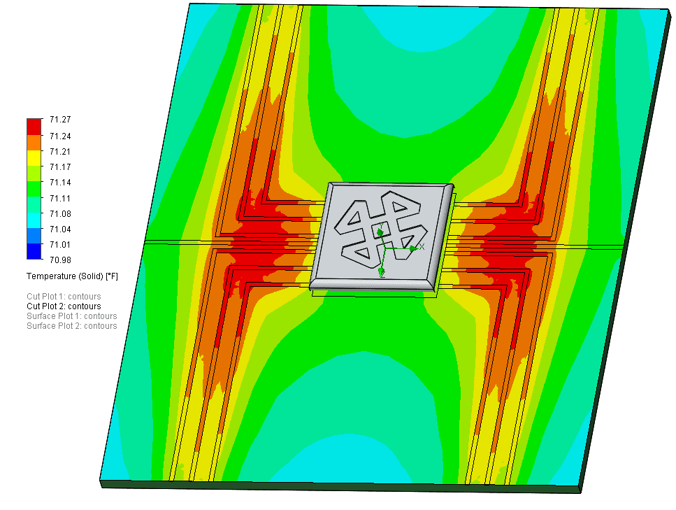
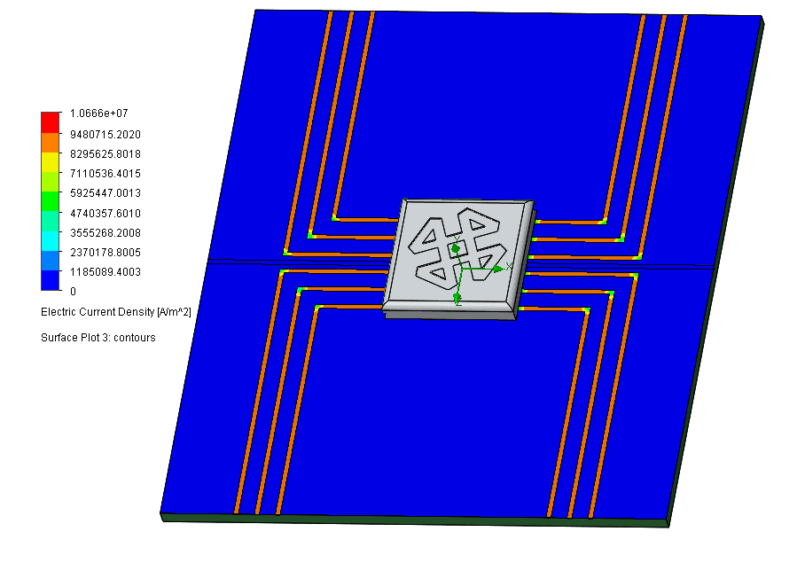
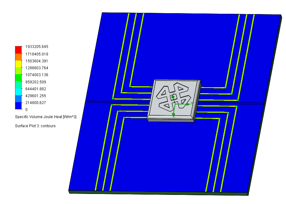
The plot shows much of the board just a couple degrees above ambient at steady state; even with 1 Amp of current going through each line. This is to be expected when using such great conductors, pure copper in this case. When dealing with joule heating you can also plot the electrical current density, specific volume joule heat, and many others. See below:
Below is an Electric Current Density Plot
Below is a Specific Volume Joule Heat Plot
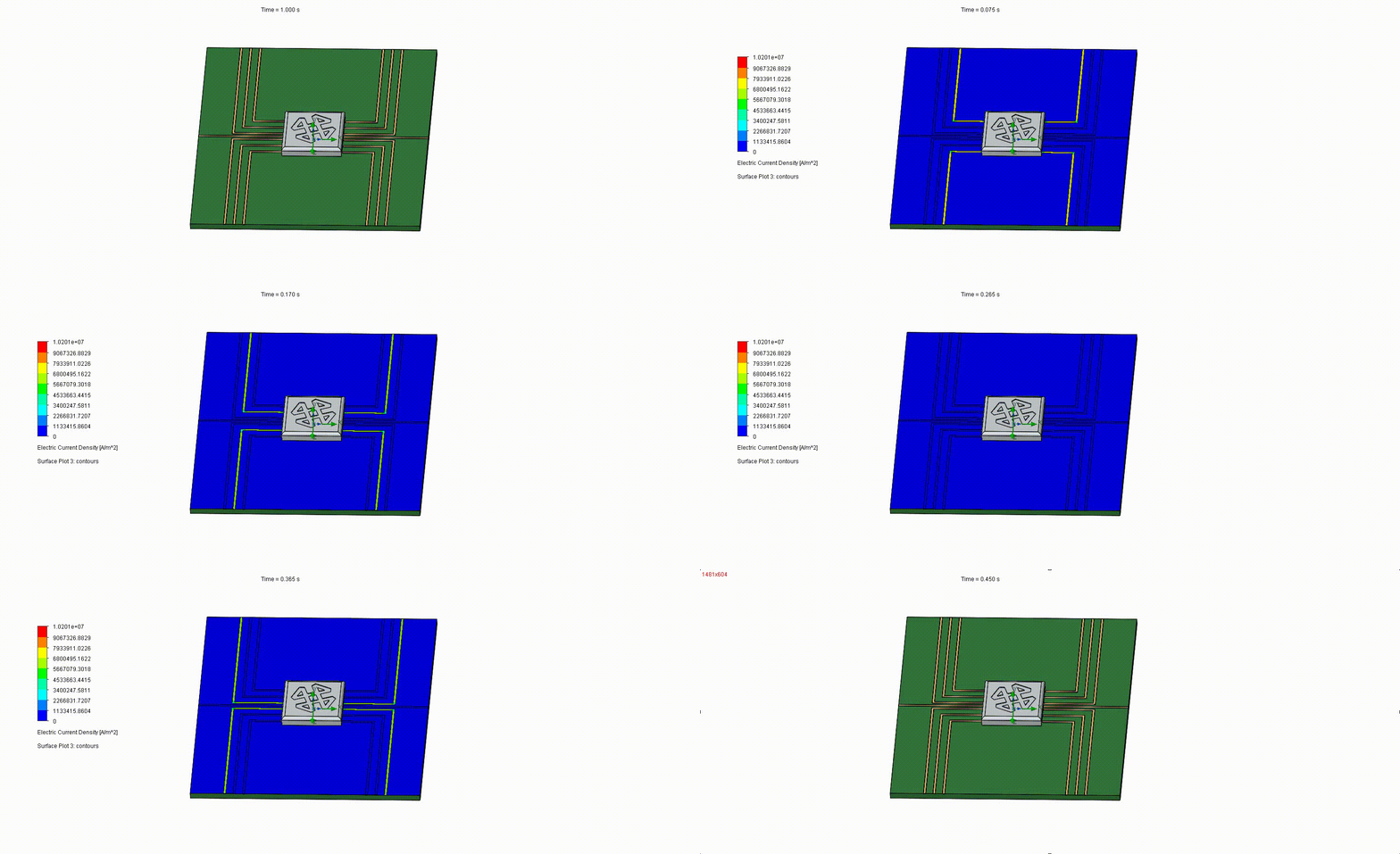
Finally, the joule heating can utilize a time dependency for transient analysis. I took the same board and added some time dependencies to the input and outputs of the electrical buses. Resulting in a really awesome animation of the current density through time.
In part 2 we will add some more advanced PCB definitions and a two resistor component to more accurately simulate the central chip.
Thank you so much for taking the time to read about Joule heating in the SOLIDWORKS Flow Simulation Electronics Cooling Module. If you found this interesting and think it may be useful to help you be more efficient in the future, reach out to your local Computer Aided Technology representative today.
Until Next Time!
Matt Sherak
Applications Engineer, Simulation
Computer Aided Technology, LLC
888-308-2284

 Blog
Blog