SOLIDWORKS 2019 What’s New – Creating Geometry-based Boundary Conditions in SOLIDWORKS Plastics – #SW2019
One of the essential steps in SOLIDWORKS Plastics is to setup the Boundary Conditions for the simulation. This includes creating the injection locations, the control valve locations, and setting the mold wall temperatures. In the past, these were somewhat limited. When placed down they are not placed exactly where you click, instead they snap to the nearest node in the mesh. This is especially an issue with coarse meshes. To be set precisely, injection and control valve locations needed to be set at vertices which will be a node location by default. The mold wall temperatures would be set to elements in the simulation.
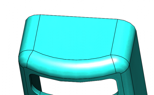
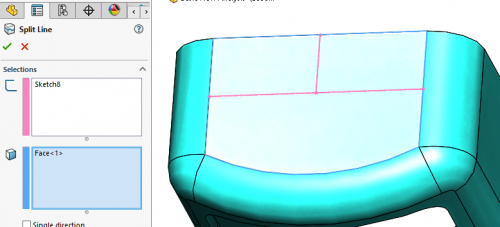
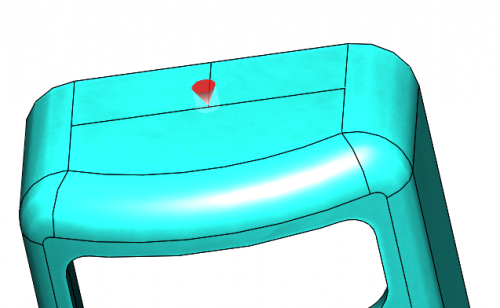
In the past, if a vertex did not exist, it could be created by using the Split lines command. For example, see the workflow below.


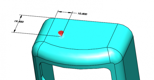
In SOLIDWORKS 2019, this setup has become much easier. The locations are no longer driven by nodal locations. Wherever you click, that is where they will be placed. Sketch points can be used as well to make the placement more precise.

I hope this part of the What’s New series gives you a better understanding of the new features and functions of SOLIDWORKS 2019. Please check back to the CATI Blog as the CATI Application Engineers will continue to break down many of the new items in SOLIDWORKS 2019. All these articles will be stored in the category of “SOLIDWORKS What’s New.”
Chad Whitbeck
Application Engineer
Computer Aided Technology, Inc
Design Innovation Month – October 2018
What is DI MONTH?
CATI is declaring October Design Innovation MONTH. We’ve created a month-long series of events and activities around design innovation especially for our customers. Attend a SOLIDWORKS 2019 event, enter our rendering contest, and learn about some cool tips and tricks at the daily online events. Plan your month at www.cati.com/design-innovation-month

 Blog
Blog 