Mesh Sectioning 2016 Enhancement
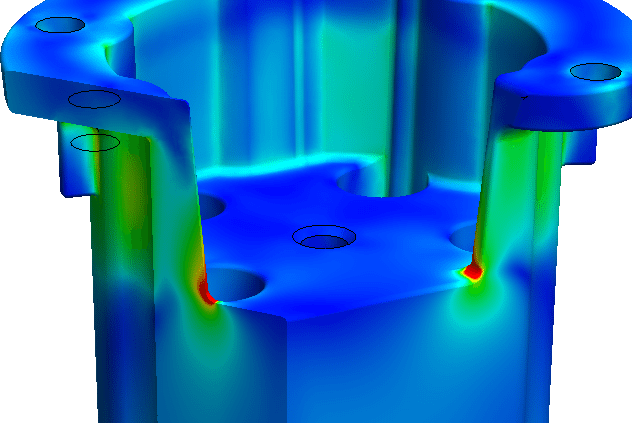
SOLIDWORKS Simulation has always allowed the user to look inside the model to see stress, strain, mesh quality and other outputs using the Results Sectioning Clipping tool. I usually call this the MRI function of SOLIDWORKS Simulation, because this functionality gives so much more insight into the model than physical strain gauge testing. The user can see how far the stress is penetrating the design. As seen below the left portion is Section Clipped showing the detail of stress inside the part.
Another capability SOLIDWORKS Simulation has always been able to apply is a view of the mesh overlayed onto the outside of the part allowing the user to determine if the mesh is refined enough or maybe too fine in certain areas.
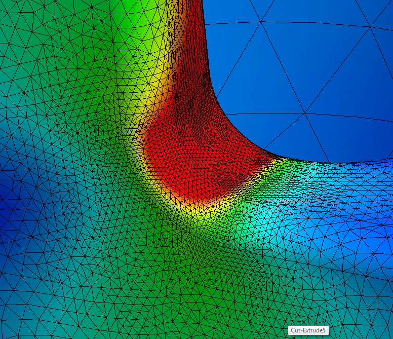
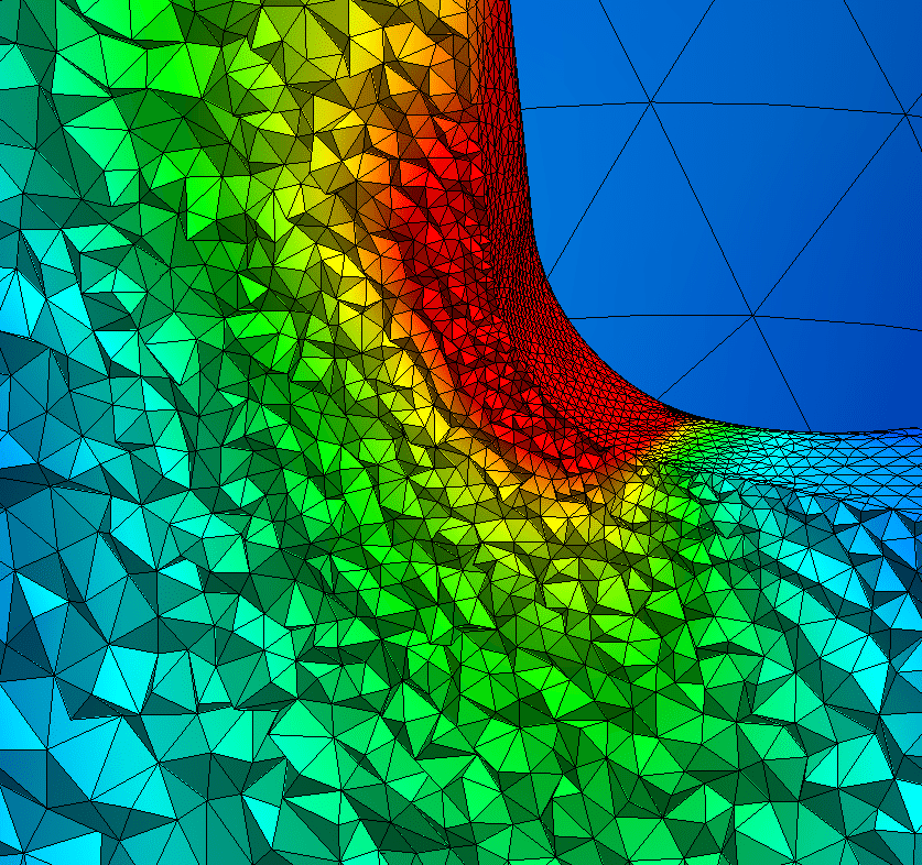
2016 SOLIDWORKS Simulation combined both of the above features to give the user an understanding of not only the parameter of the plot (stress, displacement, mesh quality, etc.) at the section but also the mesh size and shape. 2016 allows the user to overlay the mesh at the section clipping in either a 2D or 3D fashion. You can find the 2D representation in the Section Clipping property manager. Select ” Show Mesh On Section Plane”. This will display the 2D mesh output on the section.
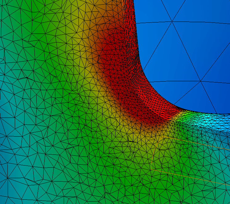
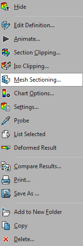
The 3D display of the mesh can be applied by selecting “Mesh Sectioning” in the right mouse button menu for Results.
A three dimensional display of the mesh is applied to the section area giving the user even greater feedback and understanding of not only the mesh but the output the sectioning is displaying. This enhancement helps the user be smarter in their design, and faster at making informed decisions regarding the output parameters.
Every year SOLIDWORKS strives to add not just new content but content that is driven by the users feedback. 2016 delivers new functionality like the Mesh Sectioning that enhance the user experience and shows that the SOLIDWORKS development team listens to its user community.

 Blog
Blog