How to Create Threads
Threading is an important feature of many parts. While cosmetic threads can be used in some cases to decrease the file size, they are often vital for the end product such as when using the part file to print in a 3D printer. For this example, threading for a cap will be created.
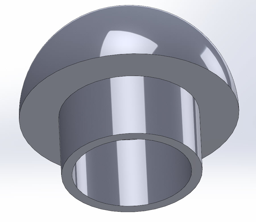
To begin, a sketch must be created on the plane where the threading should start. In this case the threading will start at the bottom of the cap. A circle is then created that shows where the spiral will be as seen from the bottom.
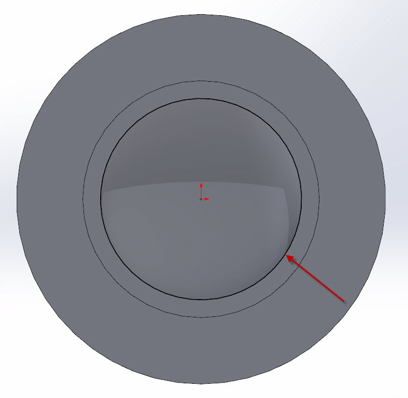
Once that has been accomplished, the Spiral/Helix command should be chosen from the Features toolbar.

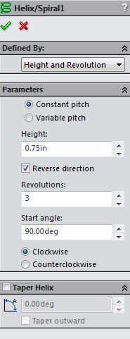
One useful tip is to set the start angle so that it coincides with an existing plane. That way the profile can be easily created.
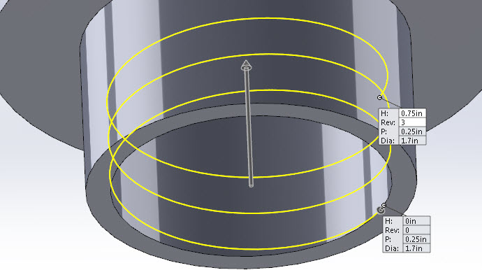
This spiral will become the path of a swept extrusion. Now, the profile for the sweep must be created. This can be any shape as long as it is coincident to the starting point of the path. Since this was done on the inside, the Display Style can be changed to Hidden Lines Removed.
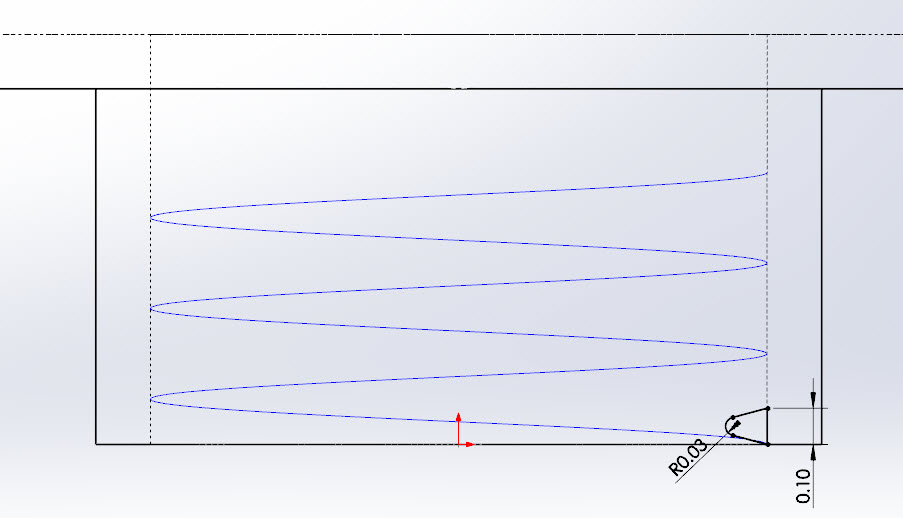
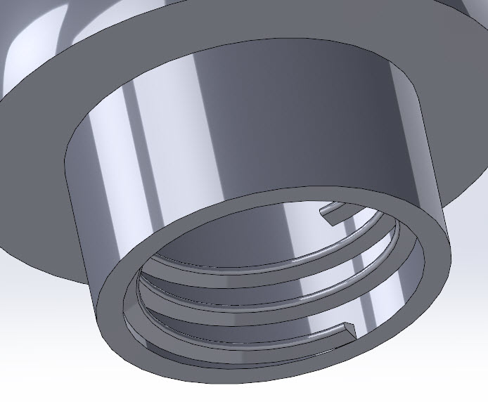
Now that both the path and the profile have been created, the Swept Boss/Base can now create the threads.
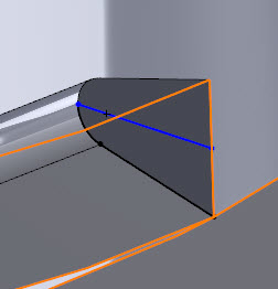
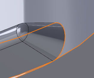
As a way to clean up the thread, the ends of the thread can revolved.
As was mentioned before, adding actual threads will increase the size of the file, in this case it increased by 37%.
Chad Whitbeck, CSWP
Applications Engineer, CATI

 Blog
Blog