Configurations or Display States Preparing for Simulation
Introduction:
Finite Element Analysis generally requires a model to be simplified of extraneous parts or features in order to analyze the model efficiently. This is common practice among analysts, and is utilized in SOLIDWORKS Simulation. In this blog I am going to discuss the two main SOLIDWORKS methods of simplifying a model and discuss the preferred method between configurations and display states.
Display States and Configurations:
Display State:
Display States allow a user to specify different hide show states, appearances, display modes, and transparencies, for a part or assembly. Display states are accessed under the configurations tab in the feature manager tree.
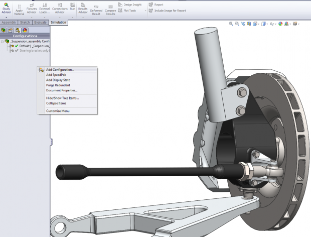
Right-click in an open area of the Configuration Manager and click Add Display State. The new display state is added to the list of display states at the bottom of the tab. Define the new display state by clicking to show the Display Pane and make changes, or by making changes on screen.
Configurations:
Configurations allow a user to create multiple variations of a part or assembly within a single document. To create a configuration, you specify a name and properties, then you modify the model to create the design variations you want.
- In part documents, configurations allow you to create families of parts with different dimensions, features, and properties, including custom properties.
- In assembly documents, configurations allow you to create:
- simplified versions of the design by suppressing components.
- families of assemblies with different configurations of the components, different parameters for assembly features, different dimensions, or configuration-specific custom properties.
- In drawing documents, you can display views of the configurations you create in part and assembly documents.
You can create configurations using any of the following methods:
- Create configurations manually.
- Use design tables to create and manage configurations in a Microsoft Excel worksheet. You can display design tables in drawings.
I bring your attention to both the Configurations and Display States because both can be used to simplify a model however one method is preferred within SolidWorks. Because the configurations use suppress and unsuppress to remove the part or feature from calculation, and not simply hide from view this is the preferred method.
In simulation when a part is hidden it is still seen as a mesh-able entity that requires a material definition, and is included in the analysis. You can at this point exclude the part from analysis however doing this upfront through configurations and suppression is the easiest method.
Example:
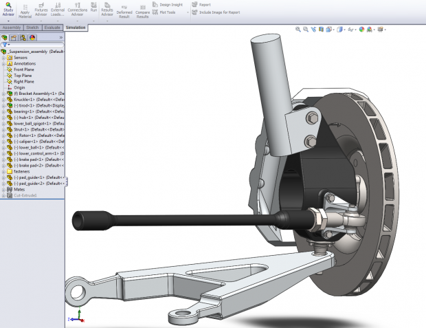
The steering bracket and connecting parts in the suspension assembly below require analysis. To leverage the existing assembly we will use the configuration method from above.
Switch to the Configuration Tab
Right Mouse Button and Choose New Configuration
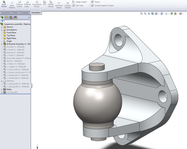
Suppress by right mouse buttoning on the components not needed in the analysis, and choose suppress
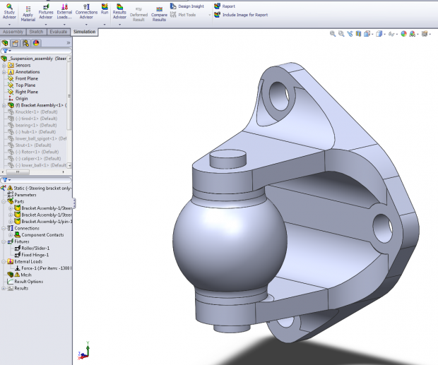
Start New Study
Only the Un-Suppressed Parts are available to analyze
Sources: 2013 SOLIDWORKS Help File
http://help.solidworks.com/2013/english/SolidWorks/sldworks/c_Configurations_Overview.htm?id=84a0a1600c6f4e77a4220606721035c6#Pg0

 Blog
Blog 


