SOLIDWORKS Design Challenge: Making a Paper Airplane
For this SOLIDWORKS blog lets jump into at a modeling challenging. During a recent training class lunch break, a paper airplane contest broke out. While I cannot claim victory in this event, I can proudly say that I did not come in last place! As the winner went home with a CATI pad of paper, today’s modeling challenge was proposed: “Can we make a paper airplane in SOLIDWORKS, using the Sheet Metal features?”
I bet we can! Let’s go ahead and give it a try!
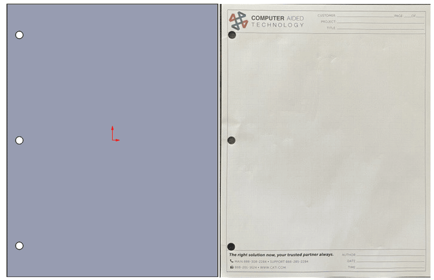
For the first step, we create our nice 8.5” x 11” sheet of paper using the sheet metal Base Flange command. In this case, our sheet metal thickness is going to be 0.004” and our bend radius will be set at 0.005”.
Using Sketch Bends
The next step, just folding it in half, is easy. We do this by creating a Sketched Bend, using a line sketched on the top face. We will only bend it 90 degrees. This should let us focus on just one side of the airplane, for now.
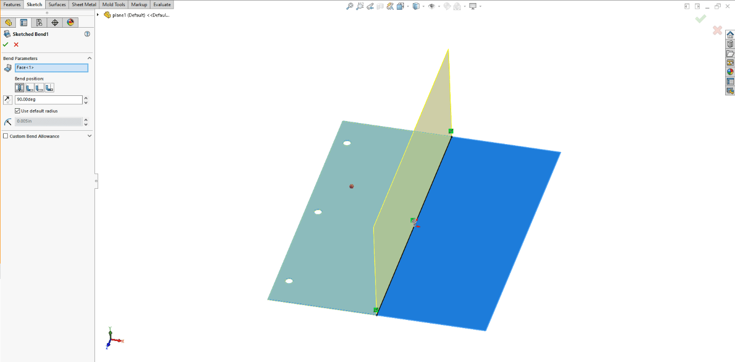
This Sketch Bend command is going to be our main tool for this project. When you have a fixed size of material, our paper, the sketched lines indicate where the center of the folds will be. As we continue to add additional bends, we need to be cautious about the bends overlapping any existing bend geometry. We cannot have bends run into other bends. This is prevented by adjusting the location of the sketched lines that are defining the bends. We can add a small 0.03” dimension to keep it above the existing bend.
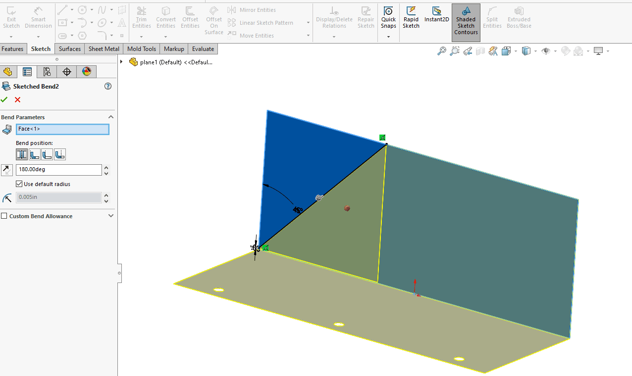
Next, we need to fold this section back over onto itself, just like the right half of this real paper plane.
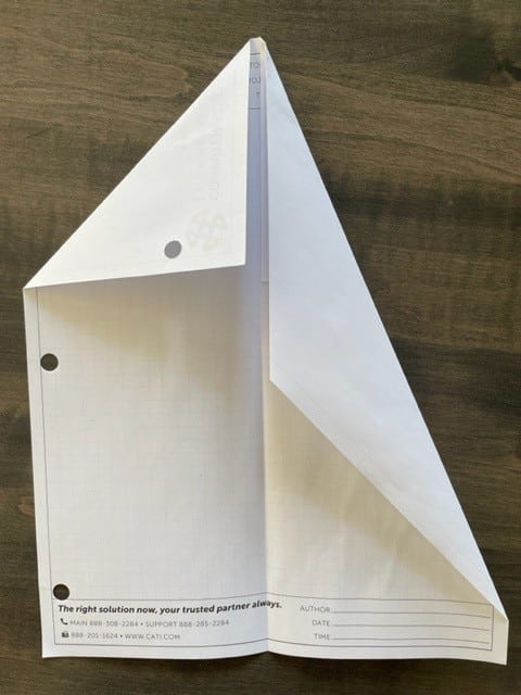
Unfortunately, here is where we run into our first major roadblock. SOLIDWORKS is unable to bend both paper layers using any of the bend tools.
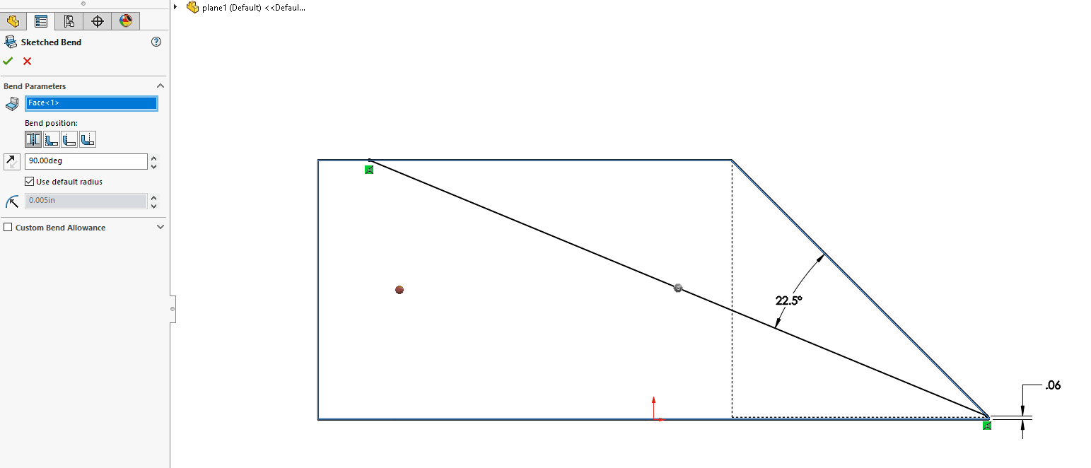
This means that we will need to model our plan differently than the way we “manufacture” it. We will just have to work backwards by modeling the paper airplane starting at a corner of the sheet of paper and working towards the center. Using an unfolded paper plane as my reference, we’ll get started….again.
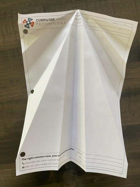
Making a Paper Airplane in SOLIDWORKS… Backwards?
Let’s keep attacking it with the Sketched Bend feature, using it for every fold in our paper airplane. Some bends will be 90 degrees, and others will be a full fold at 180 degrees. This will allow us to account for the sections where the paper is doubled over.
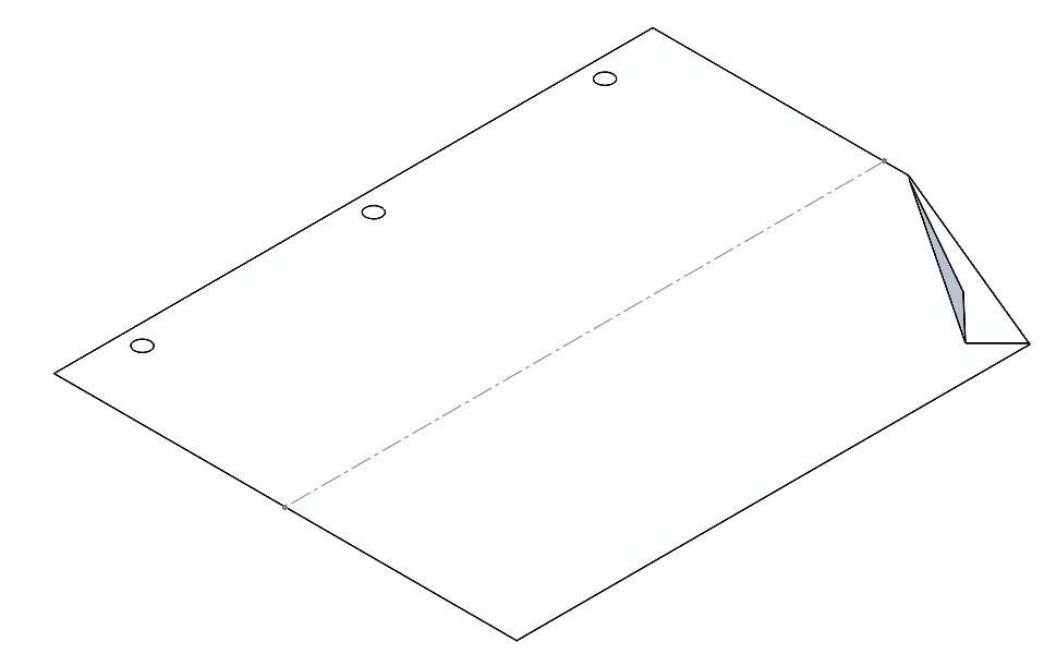
Our first Sketched Bend command is the tiny corner fold of our sheet of paper. 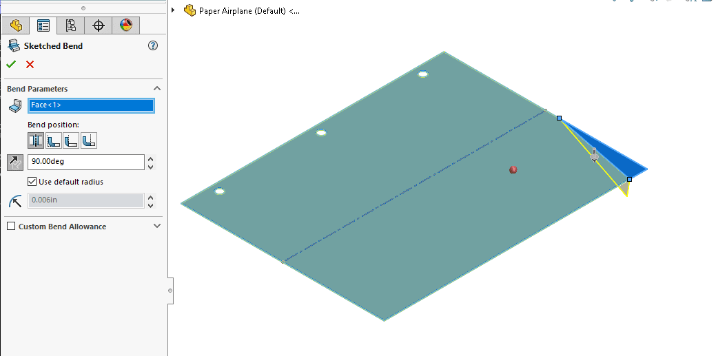
The second Sketched Bend feature bends the existing folded geometry upwards a full 180 degrees.
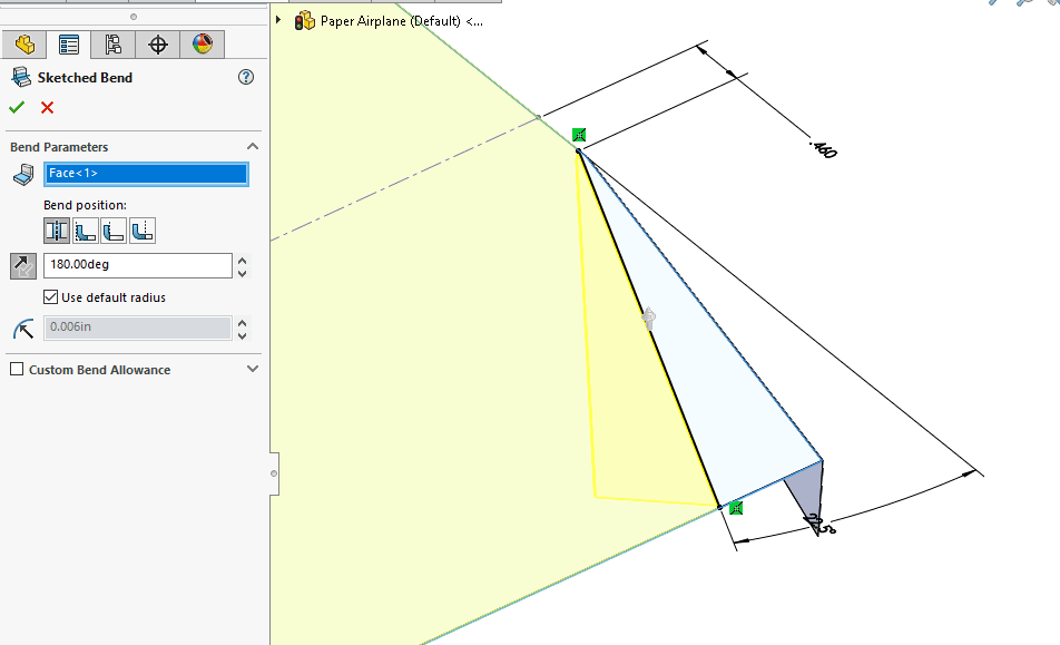
We are off to a good start! This is working better than the initial attempt, so far!
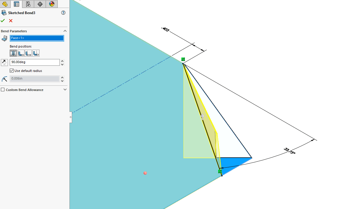
Then, we will add a third Sketched Bend feature, bending it upwards at 90 degrees.
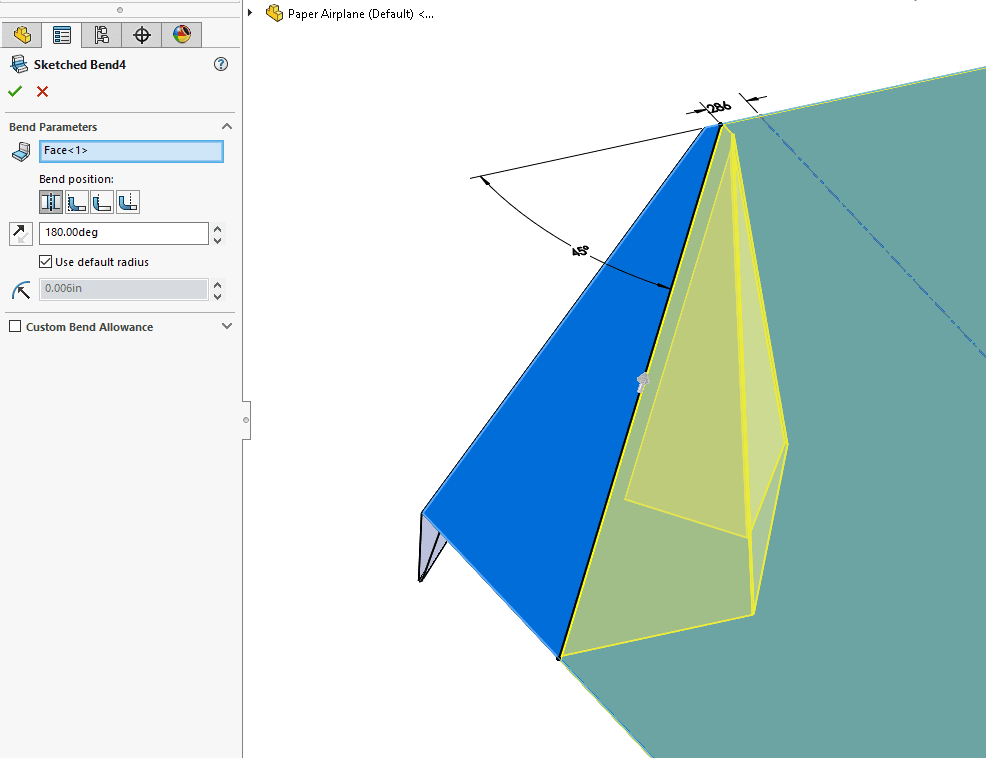
For the fourth Sketched Bend, we are folding this corner over again, this time it is a complete 180 degrees bend.
Continuing to work our way towards the center of the sheet of paper, we’ll use another Sketch bend.
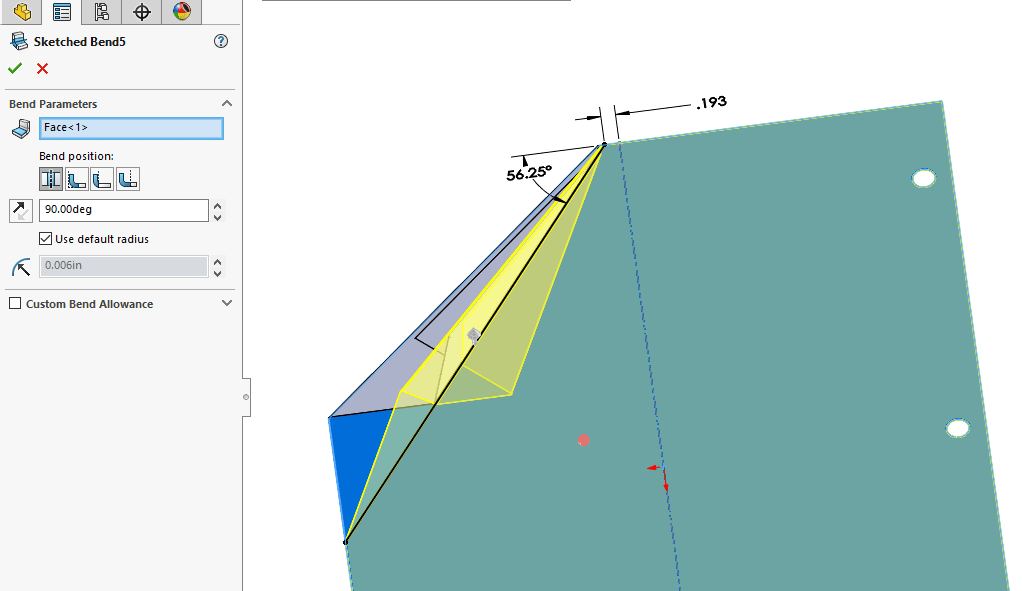
Next, let’s add Sketched Bend number 6, another 90-degree fold. So far, it’s still looking good!
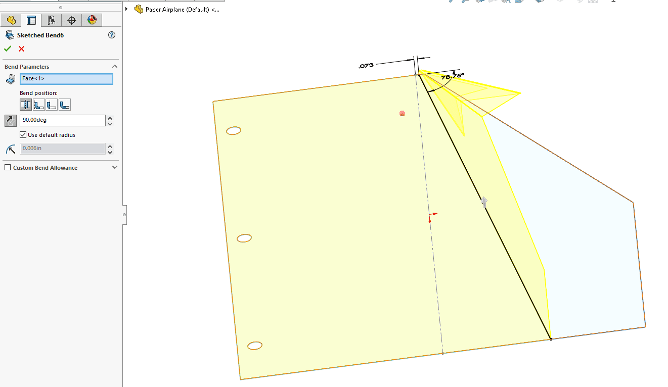
Sketched Bend number 7 folds it 180-degrees.
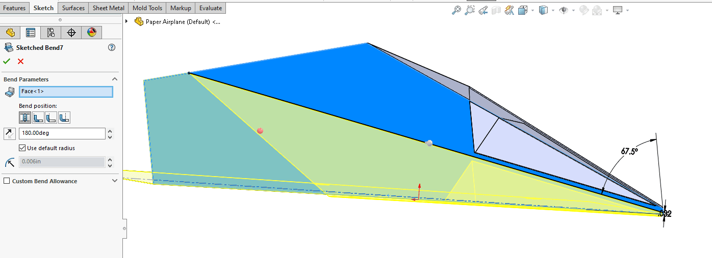
That was a glorious step! We now have half of our plane complete and It is looking great!
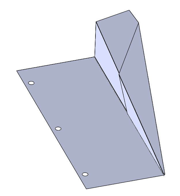
After applying the exact same Sketch Bend commands to the other side of the plane, we ended up with a great result!
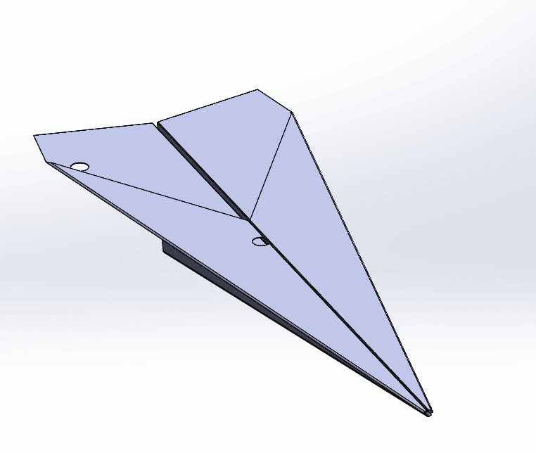
This completes the design challenge and our plane looks ready for a test flight.
Thanks for reading and please suggest any other design challenges for us to have some more fun with.
Greg Buter
Application Engineer Manager
Computer Aided Technology

 Blog
Blog