SOLIDWORKS: Creating a DXF/DWG From a Sheet Metal Part
Flat pattern information is often communicated for production through DXF and DWG formats. The 2D information provided in a DXF or DWG can be read directly by nesting applications and cut via laser or waterjet. You can even export to a punch press as well. SOLIDWORKS provides options to export the flat pattern information directly to these formats from the 3D model.
With a sheet metal part open, let’s go thru the steps to creating a DXF or DWG file.
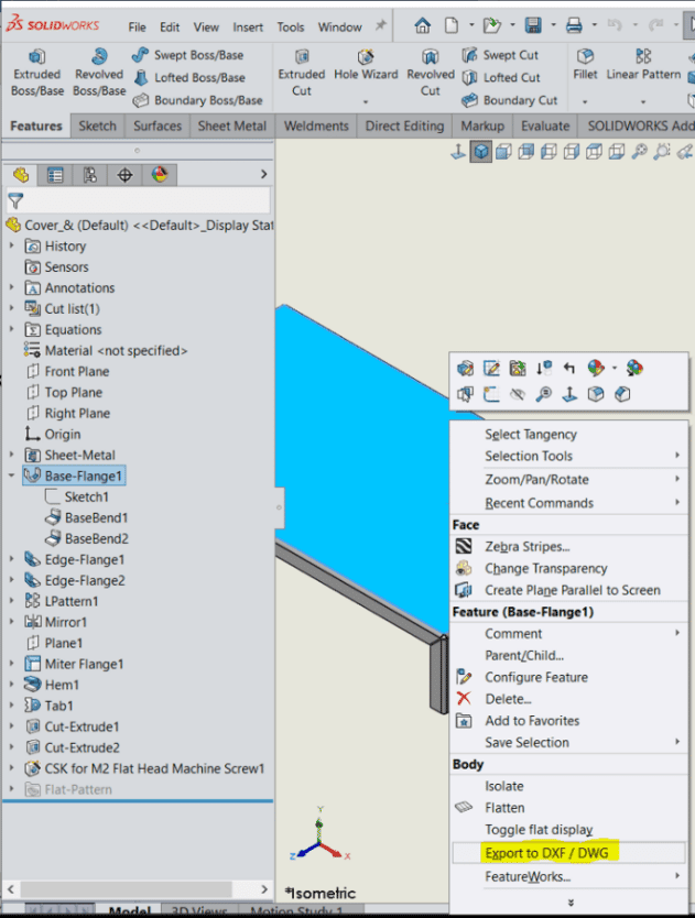
Right click any face of the sheet metal part and click Export to DXF/DWG. (Second from the bottom)
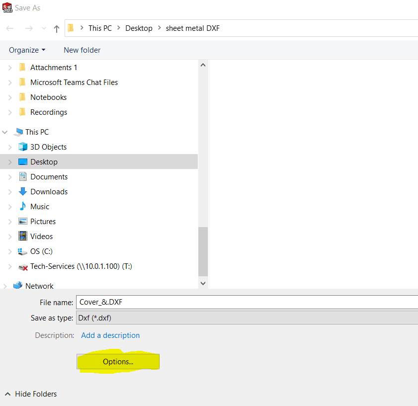
Click the Options button.
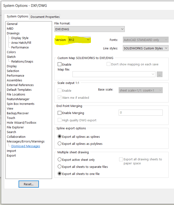
Select your version using the drop down and click Ok.
Save the DXF file in desired location. A property Manager will appear.
Click Sheet Metal radial button. Under Entities To Export, Geometry should be checked by default, select any other entities to bring over (Bend Lines, forming Tools…)
You can click on a vertex as the origin or establish your own x or y axis.
If you have one-part, Single file radial button is good. If you had a multi body part, you could separate them out by using Separate files.
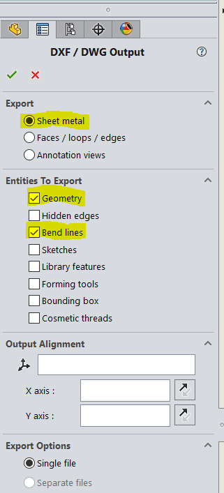
Hit the green check mark.
The DXF/DWG Cleanup dialog box appears. At the top, you can zoom to fit, zoom to window zoom in/out, pan or previous view.
You can also remove entities by left mouse clicking it and deleting from your keyboard.
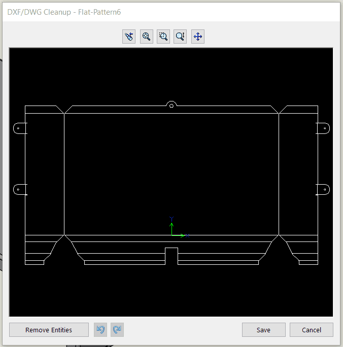
Click save and you’re good to go.
I hope you find this helpful. Thanks for reading.
Roger Ruffin
Sr. Application Engineer
Computer Aided Technology

 Blog
Blog