Real Gases in SOLIDWORKS Flow Simulation
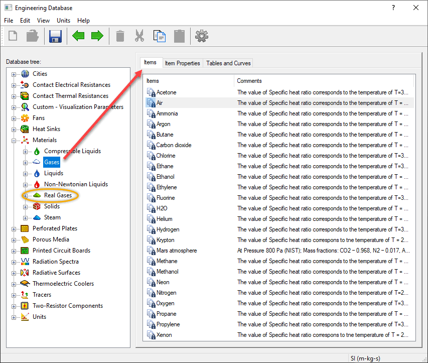
If you’ve simulated airflow through an electronic device or in a room using SOLIDWORKS Flow Simulation, you’ve likely picked “Air” from the “Gases” section of the Engineering Database. The gases found in that section are treated as ideal gases. Many other predefined gases are available, and you’ll notice from the image below that there are several that might be used in industrial or chemical processes, such as butane, ethanol, hydrogen, etc. For such applications, you might want to consider looking further down in the list of materials for the circled section titled “Real Gases”.
First, a brief word about ideal and real gases.
Gases are a continuum of molecules that are constantly in motion, colliding with one another and the vessel they are contained in. This interaction and the resulting pressure within the contained gas is related to the amount of energy in the collection of molecules, which can be determined in one of two ways – treating them as either an ideal gas or a real gas.
Ideal Gas
As the name suggests, an ideal gas represents the behavior in a way that simplifies the calculation by considering the collisions as perfectly elastic with no intermolecular attractive forces.
The relationship between pressure (P), temperature (T) and volume (V) of the gas is characterized by the equation:
PV = nRT,
where “n” is the number of moles and “R” is the universal gas constant.
Real Gas
The calculation of real gases more accurately captures the performance of the molecular interaction by modifying the ideal gas law. There are several methods to do this. In SOLIDWORKS Flow Simulation it is done by implementing the modified Redlich-Kwong equation of state. A description of this formulation can be found in the Flow Simulation help file by searching for “Real Gases”
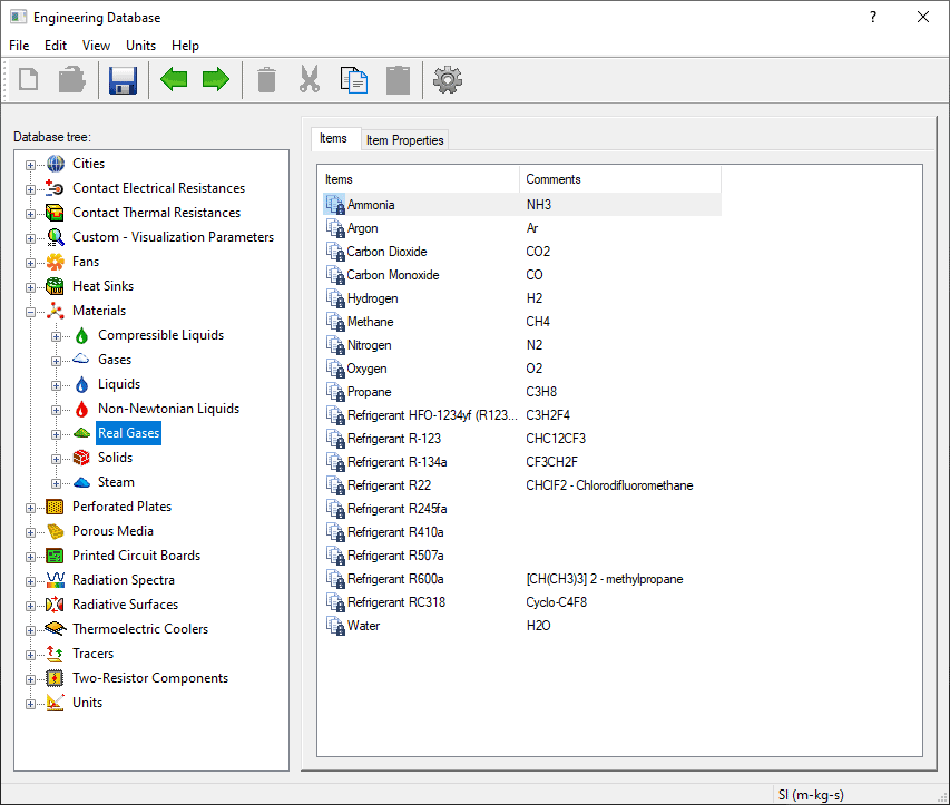
Notice from the list of “Real Gases” below that there are multiple predefined materials that were also shown in the “Gases” category, plus multiple common refrigerants.
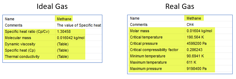
Let’s see the difference between the two property listings for methane. For ideal gases, the physical properties are explicitly defined. The “Table” designation indicates that the properties are temperature dependent. For real gases they are predicted through the state equation using the range of pressures and temperatures listed.
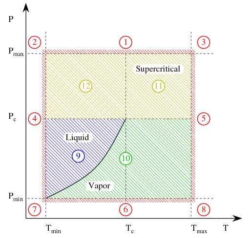
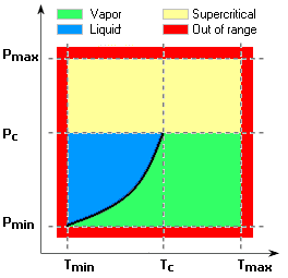
Real gas can change phase (liquid, vapor or supercritical) based on the temperature and pressure conditions. Vapor and supercritical phases are valid areas of inclusion in the Flow Simulation solution and are shown in the phase diagram below (copied from the help file.) Areas 10-12 indicate the valid areas (vapor or supercritical); if conditions fall outside these regions (areas 1-9) a warning is issued within the solver monitor window. In other words, the program can not directly represent liquid-vapor phase change, nor can it represent the gas at pressure and temperature conditions outside the min/max ranges.
During post-processing, you can check the expected phase of the material for the conditions in the simulation through a cut plot. When the plot parameter is set to “Real Gas State”, the color bar is replaced with a schematic phase diagram indicating the meaning of colors shown on the plot.
For more information on this important topic and a complete technical description of real gas behavior in SOLIDWORKS Flow Simulation, please consult the help file on the subject of “real gases”. Using this set of materials in your projects, I think you’ll find an increased level of accuracy for certain problems that simulate industrial and chemical processes.
Kurt Kurtin
Sr. Product Manager, Simulation
Computer Aided Technology

 Blog
Blog