Advanced Techniques for Recognizing Features
SOLIDWORKS FeatureWorks is a tool which converts imported geometry back into SOLIDWORKS features. FeatureWorks can convert neutral file formats such as STEP, IGES, and more into hybrid or fully-featured models. This allows geometry to be easily modified with features instead of direct editing. The problem with automatic methods of recognition is that computers do not think like a human. It does not intuitively consider the best methods of modeling designs. It does not consider design intent. That’s where advanced, interactive techniques of FeatureWorks come in.
This blog is intended for intermediate users of SOLIDWORKS FeatureWorks. If you are a beginner, I suggest visiting an article I wrote previously: Automatic Feature Recognition basics. I will first cover the reverse design methodology necessary for success using FeatureWorks, then I’ll cover interactive techniques, before wrapping up with important settings.
Reverse Design for FeatureWorks
The basic strategy of design in SOLIDWORKS is to start with additive processes (bosses), followed by subtractive processes (cuts), and lastly cosmetic features (fillets/chamfers). Adding more features grows model complexity.
The inverse is true when translating neutral files into SOLIDWORKS features. Simplify geometry first by recognizing cosmetic features, then cuts, and lastly, bosses. This reduces the complexity of the model. Simple models increase the likelihood of a fully-featured model.
Let’s look at a model, how SOLIDWORKS Automatic recognition translates it, and where improvements can be made.
![]()
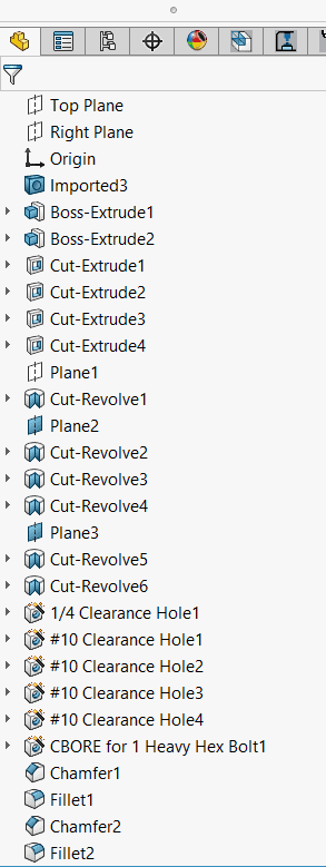
The automatic translation process leaves a partly-featured SOLIDWORKS model. Note the “Imported3” feature at the top of the feature tree. This is a hybrid model. In many cases, this would be sufficient. We can make enhancements through interactive feature mode.
Interactive Technique for FeatureWorks
To use FeatureWorks on a model that’s already open, the Recognize Features command can be also accessed through Insert> FeatureWorks. Interactive techniques can help resolve these component issues. First, attempt to recognize the smallest chamfers/fillets. On this model, some of the chamfers were not recognized.

At this point, it’s easy to get discouraged and write off the value of the tool. Instead, delete the whole chamfer using the “Delete Faces” command within the FeatureWorks PropertyManager. Make note of the chamfer size so it can be re-applied after model recognition. Even one successful chamfer feature can help to add the others when fully featured.
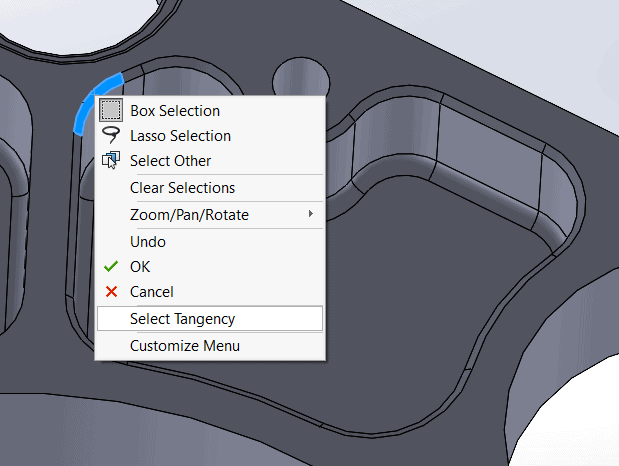
Tip: Use “Select Tangency”. When selecting a face with tangent faces, right-click and use Select Tangency to grab all the chamfered edges.
Once all cosmetic fillets are either recognized or deleted, it is time to recognize the holes and cuts. This can be achieved interactively or by switching back to automatic recognition.
![]()
The model has several areas of symmetry that can be used to mirror features to match the design intent. Click “Next” to go into the intermediate stage of FeatureWorks.
The intermediate stage of FeatureWorks adds pattern recognition and feature re-recognition. Features recognized as revolves may be better suited as extruded cuts. This allows users to re-build the model as it was in it’s native platform.
I’ll make these two cuts mirrored cuts with right plane symmetry. I can do this for any acceptable features.
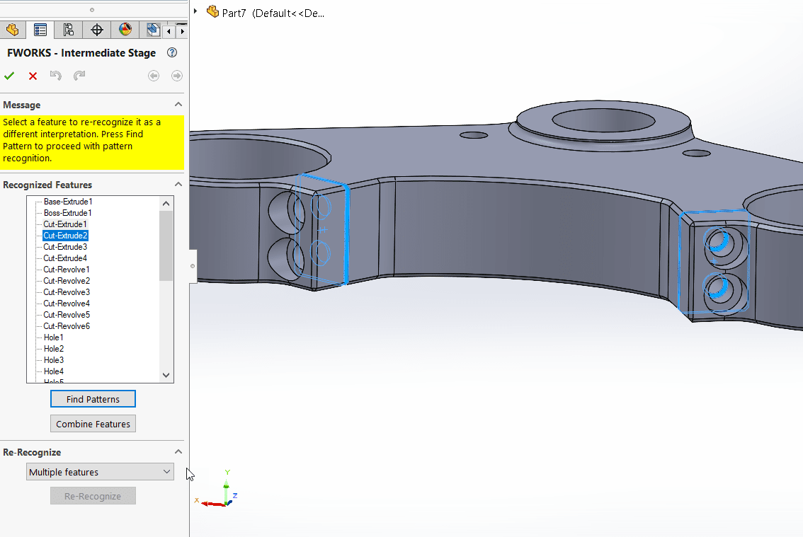
I’ll choose to recognize these features as mirrors. Users can also specify linear, rectangular (bi-directional), or circular patterns.
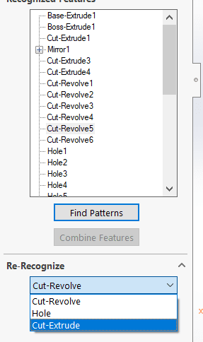
I can re-recognize different feature types like cuts as revolves, holes, or cut extrudes. This is great for the through holes at the top. I’d like to change this to an extruded cut instead. I can use the drop-down menu to change the feature type.
Note also “Combine Features”. This is great for multiple fillet or chamfer features with the same size.
It might not look perfect yet… In our example, not all cuts are recognized the same way as the native file. One final pass through the feature tree after recognition will help add any failed features. The counterbore holes are recognized as multiple holes and cut revolves. I will clean these up in the feature tree.
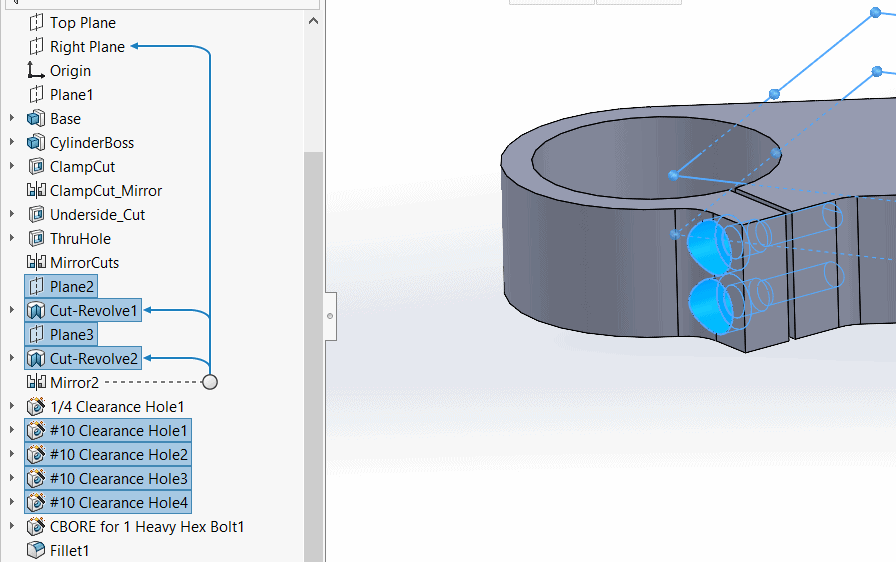 I will delete all the highlighted features that make up these Hole Wizard holes.
I’ll also make sure to combine all like fillets and chamfers.
FeatureWorks automatic vs interactive design tree comparison:
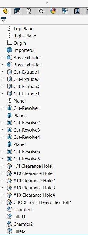
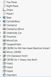
Which design tree would you prefer? Simple design trees make a significant difference. The model even rebuilds 20% faster.
Advanced Settings for FeatureWorks
There are many settings to aid in a successful conversion. To access those settings, click on the “Options” button. Options can also be accessed through Insert> FeatureWorks> Options..
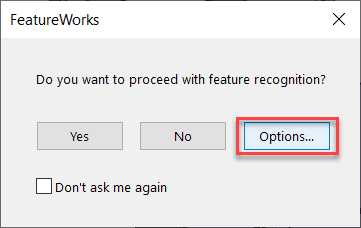
Under “General”, choose the default settings for the file. Users can either overwrite the existing neutral file or create a new file.

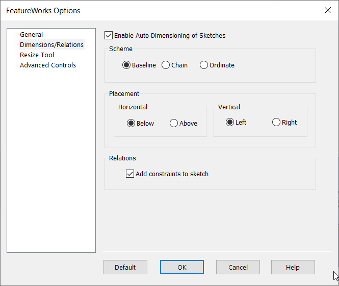
FeatureWorks leaves sketches under-defined by default. FeatureWorks can automatically add relations and dimensions to sketches. Dimensions schemes and placement can be specified. I can also add only relations. Adding dimensions and relations take longer to convert sketches. In most cases, SOLIDWORKS won’t assign the proper sketch dimensions. The user can decide the design intent of the sketch when off.
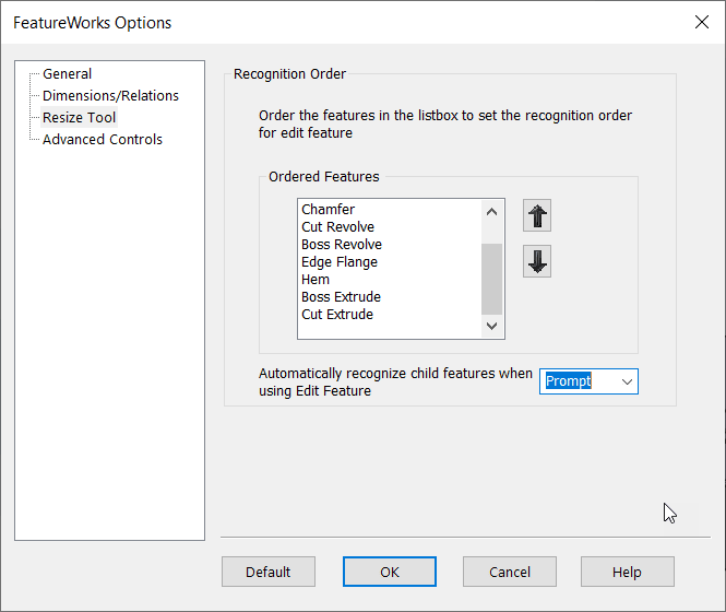
I can re-order features to accommodate certain features first under “Resize Tool”. Earlier in this blog, I talked about how re-recognizing features may be necessary. If users most commonly use revolves over boss extrudes– or vice versa– order the features to favor revolves over those extrudes. Make sure to maintain the reverse design workflow by keeping chamfers/fillets first.
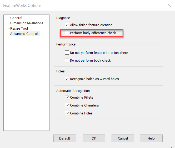
Advanced Controls options allows automatic comparison of the fully featured model and the original neutral file. This can give clear indicators of how well the features translated, or which features are still missing.
Conclusion
SOLIDWORKS FeatureWorks is an extremely powerful tool. Like any tool, you need to know how to use it to make it work for your application. It isn’t always necessary to have a fully featured model, or even a partially featured model. Make sure you can justify your time by first establishing the need for a featured model.
This post covered the strategy of reverse design when using FeatureWorks. We must simplify geometry by removing fillets/chamfers, then removing cuts, then removing bosses. When using this interactive design methodology, we can have a better result. The interactive techniques include deleting chamfers and fillets that cannot be recognized, recognizing patterns where possible (and purposeful), and re-recognizing features to convey better design intent. Lastly, additional settings can help with file maintenance, automate fully defined sketches, and order how automatic feature recognition decides which feature types it will use first.
If you want to learn how to leverage your non-SOLIDWORKS CAD data, contact Computer Aided Technology to learn more. Until then, good luck and happy designing!
Jordan Kleinschmidt, CSWE
Application Engineer II
Computer Aided Technology

 Blog
Blog