SOLIDWORKS: Basics of Reference Geometry Axis
Reference Geometry includes reference planes, axes, coordinate systems, and points. In this blog, we will discuss the many ways of creating and defining a Reference Axis.
The Reference Geometry command lives on the Features toolbar, but you can also access it from Insert > Reference Geometry.

The Reference Axis PropertyManager includes a Selections box where you will define your Reference Axis. The combinations of these selections that will fully define the Reference Axis are described and depicted below the Selections box.
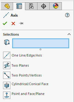
We will look at an example of each of the selections for defining the Reference Axis:
- One Line/Edge/Axis
- Two Planes
- Two Points/Vertices
- Cylindrical/Conical Face
- Point and Face/Plane
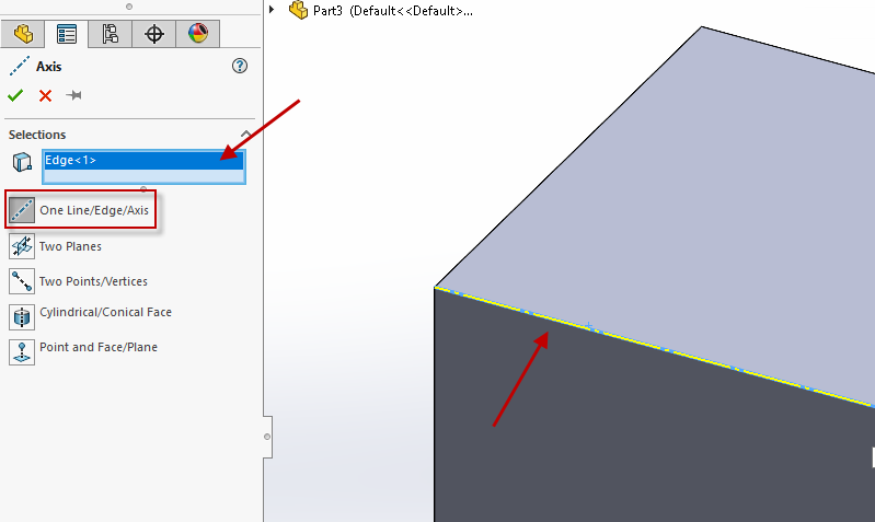
One Line/Edge/Axis
Selecting any one line, edge, or axis will create a Reference Axis along that line, edge or axis.
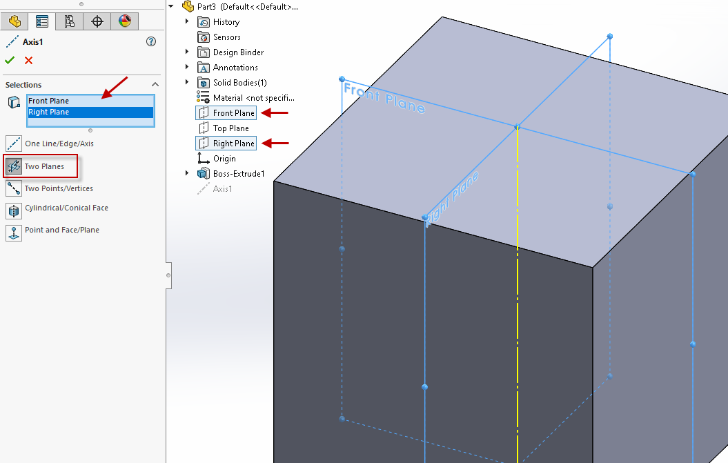
Two Planes
A Reference Axis can be created at the intersection of two selected planes.
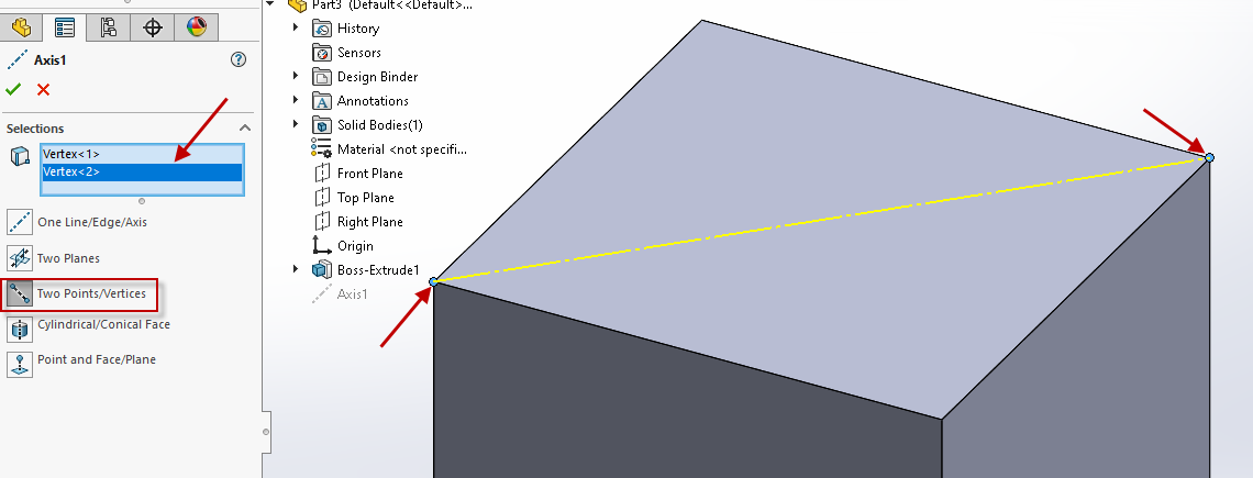
Two Points/Vertices
Since two points make a line and a line is an acceptable selection for defining a Reference Axis, we can simply select two points or vertices to define a Reference Axis.
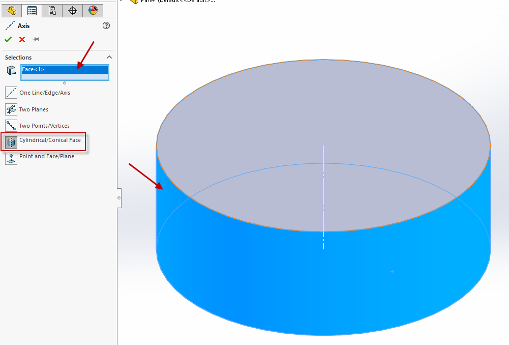
Cylindrical/Conical Face
Selecting a cylindrical or conical face will create a Reference Axis that goes through the center of the circle that defines the cylinder or cone.
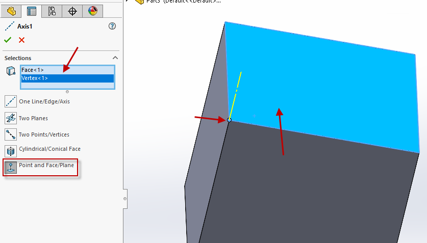
Point and Face/Plane
The final way to create a Reference Axis is to select a point and a face or plane. The Reference Axis will be created coincident to the point and normal to the face or plane.
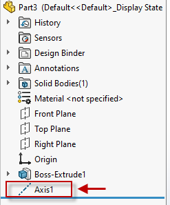
In all scenarios, the Reference Axis will show up as a feature in your FeatureManager Design Tree.
I hope this gives you a better understanding of ways to create a Reference Geometry Axis to make you more efficient in SOLIDWORKS!
Nicole Kelley
Support Engineer
Computer Aided Technology, LLC

 Blog
Blog