SOLIDWORKS Flow Simulation: Hydrology Applications
With the addition of the free surface capability, SOLIDWORKS Flow Simulation can now perform simulations of more real-world applications. One commonly encountered Civil Engineering application in open-channel flow design is an energy-dissipation phenomenon called hydraulic jump, which occurs when a fast-moving, shallow flow encounters a relatively slow-moving, deep flow field.
Fluid Mechanics texts classify open-channel flow using the dimensionless Froude number (Fr), which is a function of the fluid velocity (V) and depth (y) (ref. F. M White, Fluid Mechanics).

Subcritical Fr < 1.0
Critical Fr = 1.0
Supercritical Fr > 1.0
When a supercritical flow field encounters a subcritical field, energy is dissipated through turbulence in a standing wave – the hydraulic jump. Such a condition is demonstrated by the flow of water down a slope that encounters a deeper pool.


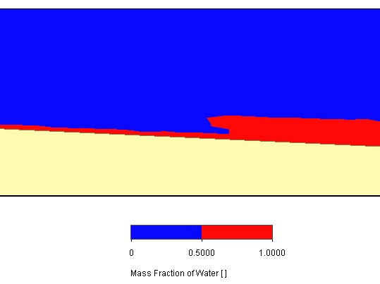
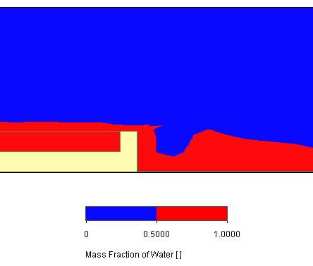
In the 2D cut plot above, water (red color) flows from left to right and generates two hydraulic jumps; one where the thin flow stream down the slope encounters the pool,
and another past the right end of the pool.
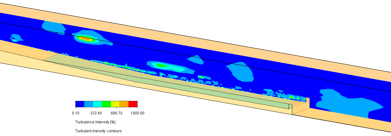
A plot of the turbulence intensity (ratio of the standard deviation of the random velocity fluctuations to the mean velocity) shows the energy dissipation in these areas and in the disturbed air above them.
There are numerous flow measurement and erosion control hydrology applications that leverage this physical behavior, such as weirs, sluice gates, stilling basins and spillways. The second jump mentioned above comes close to simulating a weir, which is an effective open-channel flow meter that incorporates an obstruction to the flow.
To investigate this more closely, a simulation of a sharp-crested weir (1-ft tall) was performed in SOLIDWORKS Flow Simulation with an upstream flowrate of 0.01 ft^3/s, and the results were compared to analytical approximations.
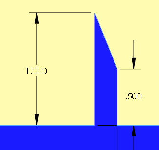

An approximate solution is given by F. M. White with reference to the following figure and variables.
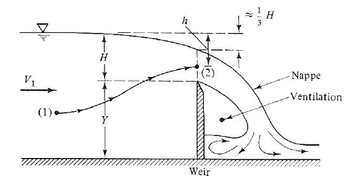
(Ref. F.M. White, Fluid Mechanics)
The volumetric flowrate per channel width (q) over a weir was developed from the Bernoulli equation by French engineer Boussinesq in the early 20th century:

where the weir coefficient is given by:

Taking rough measurements in SOLIDWORKS of the nappe height above the weir from the Flow Simulation results shown below,
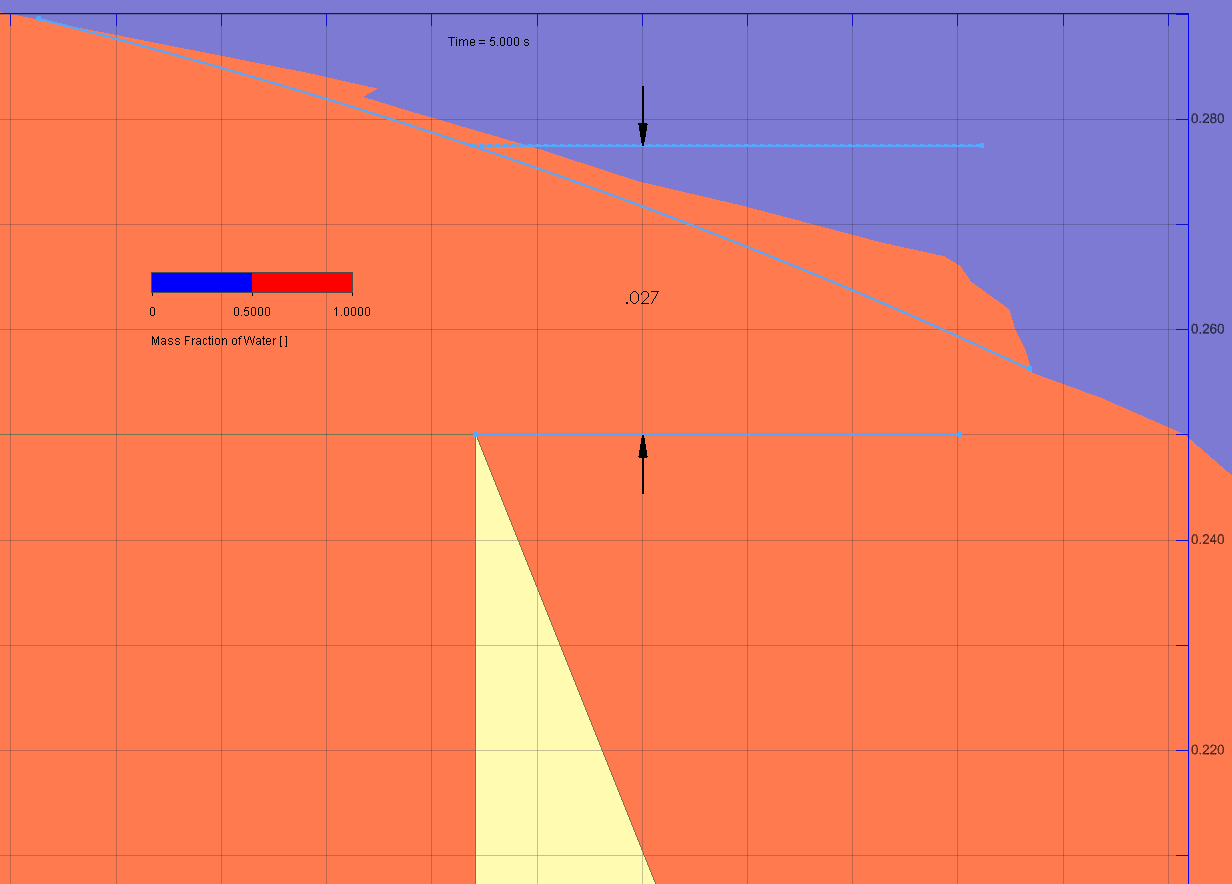
we can calculate the following:
H = 0.041 ft (measurement of the nappe height above the weir (0.027 ft) is approx. 2/3 of H)
Cw = 0.614
q = 0.013 ft^3/(s-ft)
The width of the 2D computational domain cell in the simulation is 1 ft, therefore the total flowrate (Q) is 0.013 ft^3/s, which roughly agrees with the flow input value of 0.01 ft^3/s. The free surface solution accuracy is influenced by the level of mesh refinement, so further refinements should yield greater accuracy.
The addition of the free surface functionality opens up many applications for SOLIDWORKS Flow Simulation – it’s now also a great tool for Civil Engineers!
If you’d like to check out other blogs related to free surface written by my colleagues, please use the links below.
SOLIDWORKS Flow Simulation – Which will fill first?
Fill Your Free Surface Volume Instantly with Flow Simulation’s Initial Condition
Thanks for reading and have fun using this great tool in Flow Simulation.
Kurt Kurtin
Technical Manager – Simulation Products
Computer Aided Technology, LLC

 Blog
Blog