SOLIDWORKS 2020 What’s New - Adding Reference Axes and Reference Planes to Mesh Bodies
As 3D scanning and printing technology continues to become more available, design workflows can be adjusted to take advantage of it. These exciting tools utilize their own software that will ultimately produce files that represent the 3D part geometry. We will look at new functionality in SOLIDWORKS 2020 that allows us to create reference geometry based on this imported scanned data.
Scanned geometry can be brought into SOLIDWORKS as a “Mesh Body”. The model is broken down into tens or even hundreds of thousands of tiny triangular faces. One issue with this mesh body is that these triangular faces are planar faces. This poses a problem where nonplanar geometry is represented incorrectly. Round geometry, filleted edges, circular holes, etc. are going to be broken down into lots of tiny flat triangle faces. The file size and rebuild times greatly increase on these parts due to the number of faces and edges that are processed.
We have other blog posts going into more detail on other SOLIDWORKS tools to work with these mesh bodies. Here, we are looking at how you can add reference geometry to these mesh body parts. This can be very helpful for cases where you need to remodel the geometry with our standard solid features. These reference axis and planes are also useful for creating mates in assemblies. Let’s look at how to do this in SOLIDWORKS 2020.
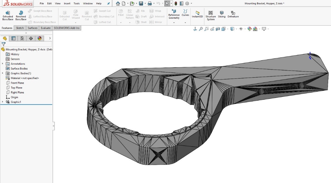
Here is an imported mesh body with thousands of triangular faces. The physical part geometry has a large cylindrical hole through the top and several small holes through the sides of the part.
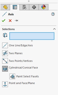
To create an Axis in this part, we bring up the reference geometry, Axis tool. We can expand the cylindrical/conical face option and pick “Paint Select Facets”. This allows us to select several planar faces that we want SOLIDWORKS to interpolate into cylindrical geometry to create the axis of.
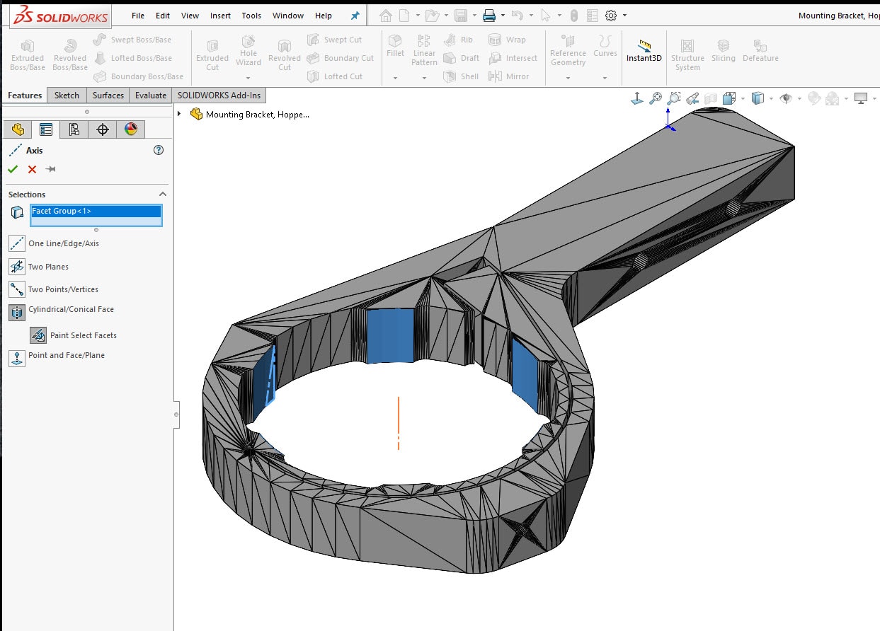
Selecting some of these main faces of the “cylindrical” geometry shows us the axis preview.
Repeating this same procedure for this counterbore hole on the side will add another Axis. 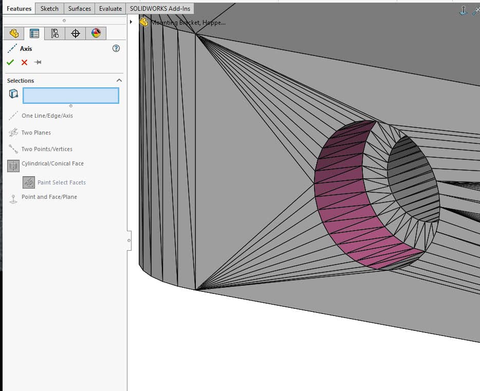
Repeating this several more times gives us additional axes. These can be used to remodel the part as a solid body or to reference the actual hole locations. 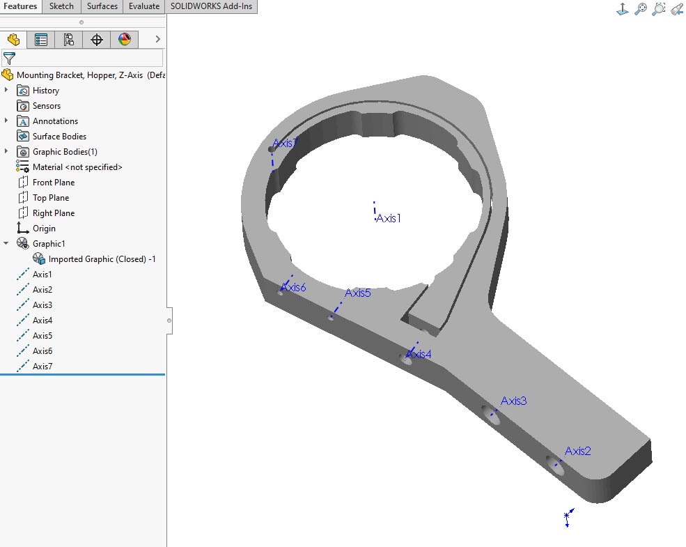
Creating reference planes with these mesh bodies is also possible in SOLIDWORKS 2020. In this case, let’s create a mid-plane through the part. This is done with the same Reference Geometry toolbar, selecting the Plane tool. This part is a mesh graphics body, so you are unable to select the individual faces. Clicking on the model will just highlight the entire graphics object.
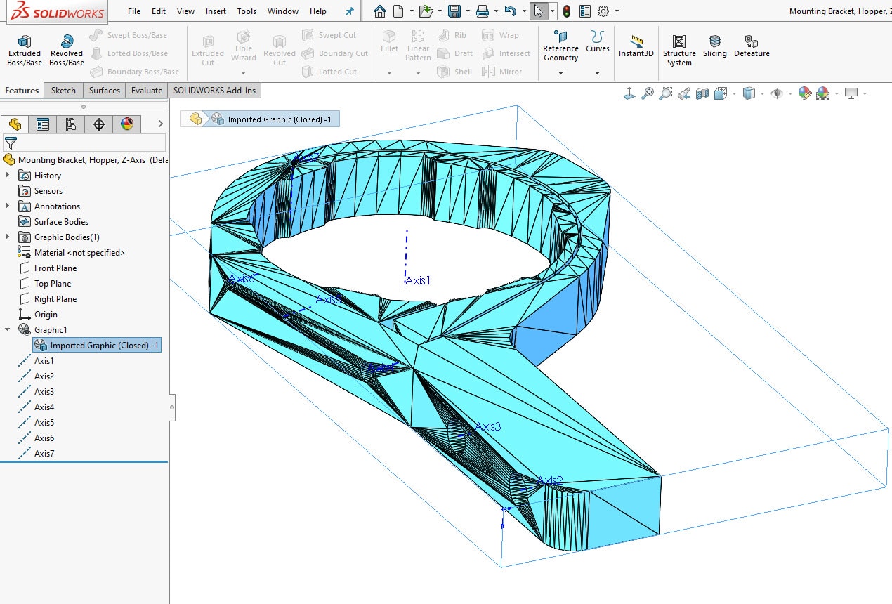
In this case, we want to select some of the individual facets to define the plane. The only way to do this is by using the selection filter for the “Mesh Facets”.
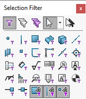
Now, preselect the opposing facets on the top and bottom of the part.
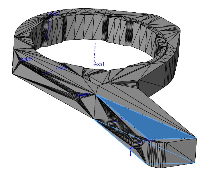
Creating the mid-plane is now possible with these two selections.
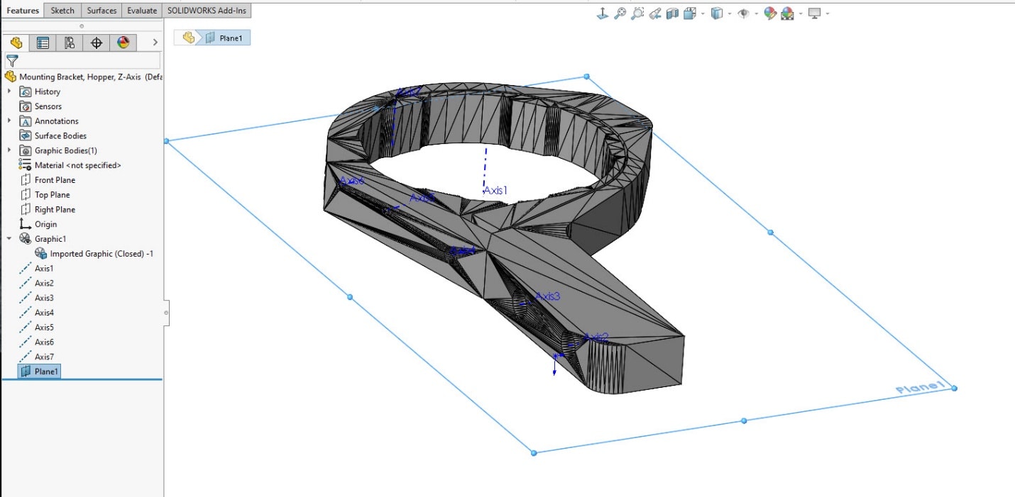
And, just like that, we were able to add some reference geometry to our imported mesh body using some new features found in SOLIDWORKS 2020.
I hope this part of the What’s New series gives you a better understanding of the new features and functions of SOLIDWORKS 2020. Please check back to the CATI Blog as the CATI Application Engineers will continue to break down many of the new items in SOLIDWORKS 2020. All these articles will be stored in the category of “SOLIDWORKS What’s New.”
Design Innovation Month – October 2019
What is DI Month? We’re declaring October Design Innovation Month—again! It’s a month-long series of special events focused on what’s new in design and manufacturing technology. You’ll learn about enhancements in SOLIDWORKS 2020 that deliver new capabilities for improved performance, streamlined workflows, and a connected design ecosystem. Find out what’s new in 3D printing applications and 3D scanning to integrate into your design process. So, get ready to do things differently. It’s time to innovate!
Greg Buter
Application Engineer
Computer Aided Technology, LLC


 Blog
Blog