SOLIDWORKS 2020 What’s New – Applying Torsional Continuity Relations
If anyone has used surface modeling before they know that creating a seamless transition between a spline and a sketch entity is the key for a good surface. In SOLIDWORKS 2019 and earlier, there were two relations that could be used to transition from a spline to a sketch entity or model edge, ‘Tangent’ and ‘Equal Curvature’. In SOLIDWORKS 2020, a sketch relation has been added to help with smoothing out these transitions called, ‘Torsion Continuity’.

To explain what this means, it will be helpful to have a better understanding of splines. SOLIDWORKS uses two types of splines, ‘Style Splines’ and ‘B-splines’. Style splines are based on Bézier curves, which make use of control points to construct a parametric equation. Ultimately, the parametric equation is how the spline is defined in the graphics window and can be simplified to a set of piecewise polynomials of a predetermined degree n. B-splines, a.k.a. basis splines, are piecewise polynomials of degree n-1, where n is the number of points used to create the spline.
So, what does this mean? We have two ways to sketch a spline that is composed of one or more polynomials. This is how the tangent, equal curvature, and torsion continuity relations are used to define the transitions between splines and sketch entities. Given a polynomial of degree 5, y(x),
y(x) = Ax5 + Bx4 + Cx3 + Dx2 + Ex + F
and a function used to create the second sketch entity, f(x), then derivatives can be used to establish smoothness between curves;
Tangent – dy/dx = f’(x)
Equal Curvature – d2y/dx2 = f’’(x)
Torsion Continuity – d3y/dx3 = f’’’(x)
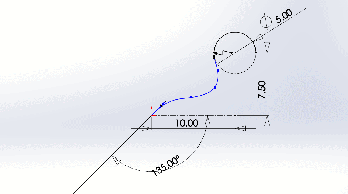
These 3 equations are solved to calculate constants E, D, and C. Let’s see what this looks like in SOLIDWORKS. Here is a spline with tangent and equal curvature relations to the arc –

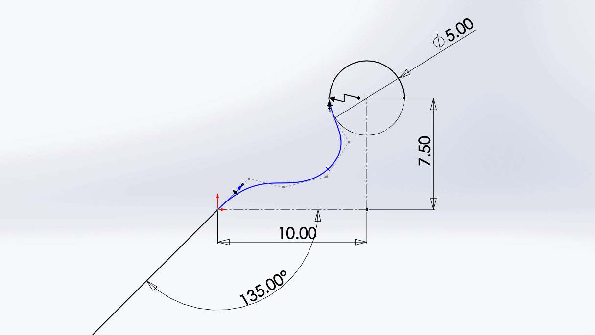
And, here is a spline with tangent, equal curvature, and torsion continuity relations to the arc –

Although the difference may seem subtle, this smooth transition on a surface may mean fewer hours of tweaking spline point locations or tangency vectors.
This relation can be applied between a B-spline or style spline and a spline, arc, conic arc, elliptical arc, linear model edges, circular model edges, conic model edges, parabolic model edges, elliptical model edges, or spline-based model edges that share one endpoint.
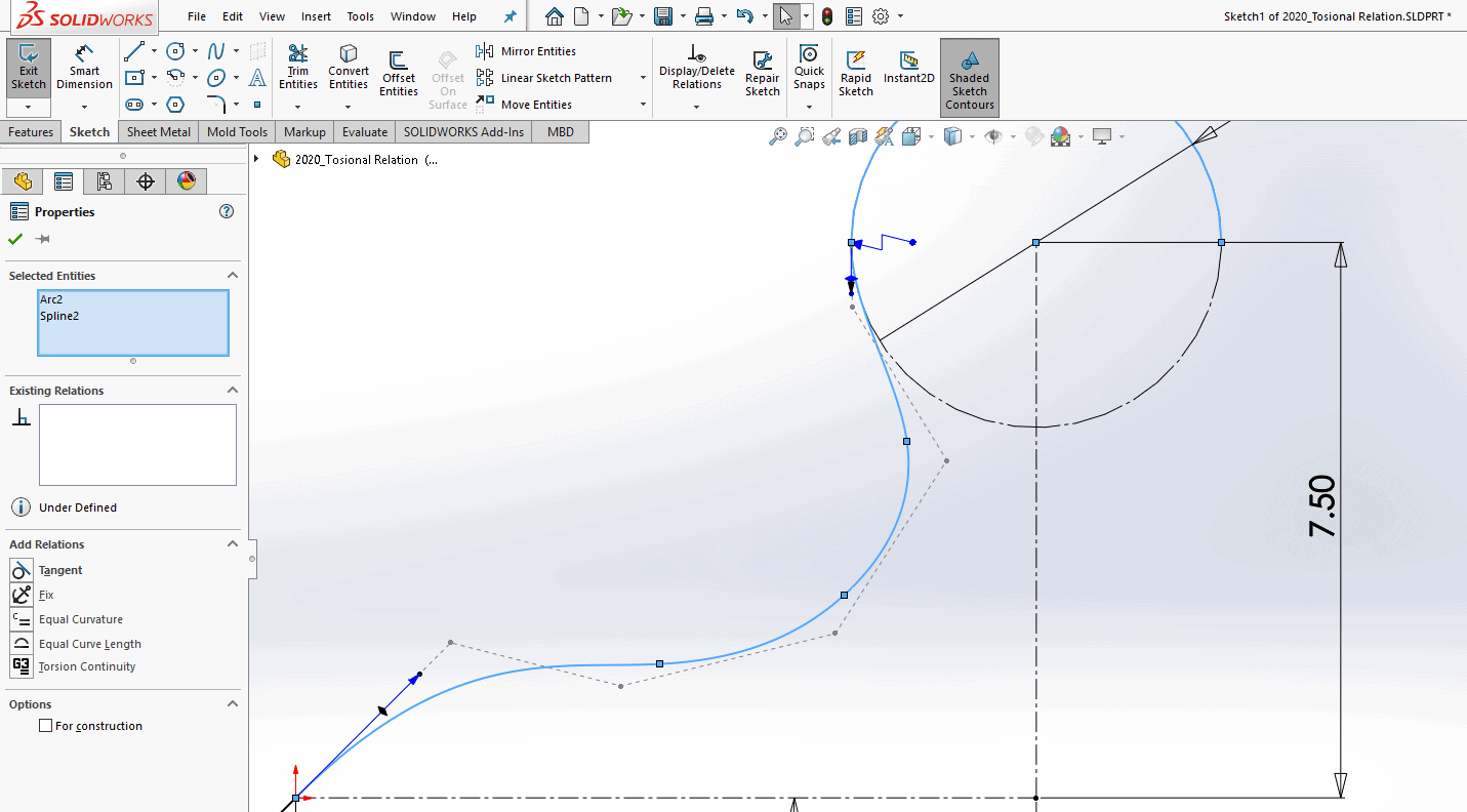
To apply a Torsion Continuity relation, select a spline in the graphics window and a second entity listed in the paragraph above by holding down the Ctrl key.

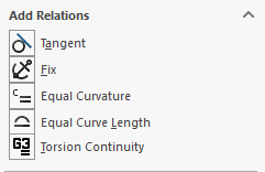
Then select the ‘Torsion Continuity’ relation in the ‘Properties’ window under ‘Add Relations’.
I hope this part of the What’s New series gives you a better understanding of the new features and functions of SOLIDWORKS 2020. Please check back to the CATI Blog as the CATI Application Engineers will continue to break down many of the new items in SOLIDWORKS 2020. All these articles will be stored in the category of “SOLIDWORKS What’s New.”
Design Innovation Month – October 2019
What is DI Month? We’re declaring October Design Innovation Month—again! It’s a month-long series of special events focused on what’s new in design and manufacturing technology. You’ll learn about enhancements in SOLIDWORKS 2020 that deliver new capabilities for improved performance, streamlined workflows, and a connected design ecosystem. Find out what’s new in 3D printing applications and 3D scanning to integrate into your design process. So, get ready to do things differently. It’s time to innovate!
Cameron Bennethum
Technical Support Engineer, Simulation
Computer Aided Technology, LLC

 Blog
Blog 