SOLIDWORKS 2018 What’s New – Mesh Files – #SW2018
SOLIDWORKS 2018 What’s New – Mesh Files – #SW2018
SOLIDWORKS 2018 comes with several new features and enhancements that give the user more power over imported mesh (*.stl, *.obj, *.off, *.ply or *.ply2 filetypes) models. Whether you are reverse engineering 3D scan data or simply looking to change the visual properties of meshes, SOLIDWORKS 2018 offers the tools you need to get the job done.
Meshes Imported as Graphics Bodies
In SOLIDWORKS 2018, mesh files that are imported as graphics bodies have several new options.
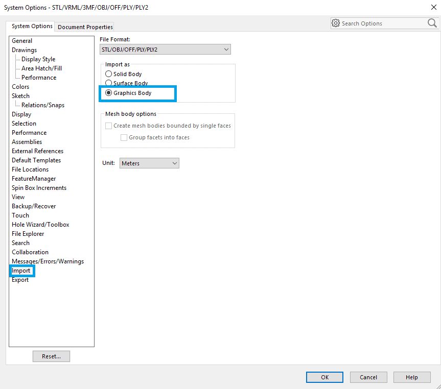
NOTE: To import mesh files as graphics bodies, go to Tools > Options > System Options > Import, and choose ‘STL/OBJ/OFF/PLY/PLY2’ under File Format. Pick the ‘Graphics Body’ radio button.
Imported graphics bodies are now collected into a new Graphics Bodies folder in the FeatureManager tree.
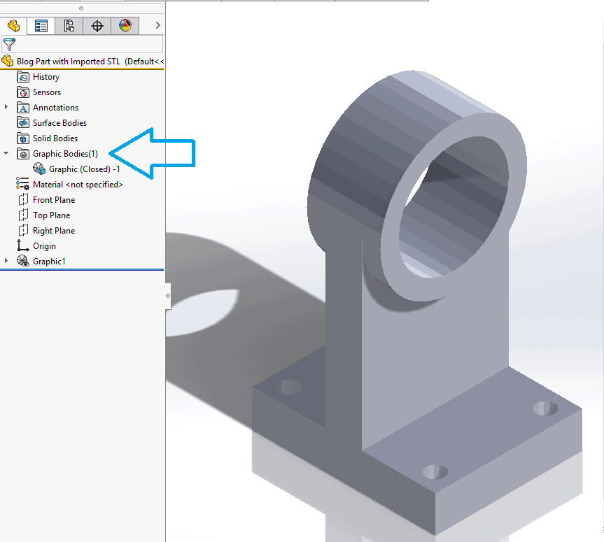
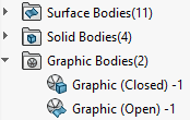
Graphics body features can be directly selected from this folder, allowing you to more easily keep track of the bodies in a multibody part. This is especially useful when building surfaces and solids from imported meshes. You can also quickly check if your meshes are open or closed without having to hunt the graphics body feature down in the tree.
Graphics bodies also have new display options. You can now add appearances to graphics bodies, as well as view them in HLR, HLV, and Wireframe.
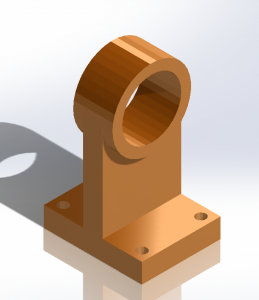
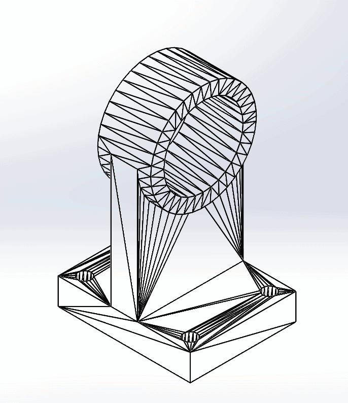
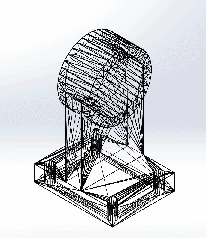
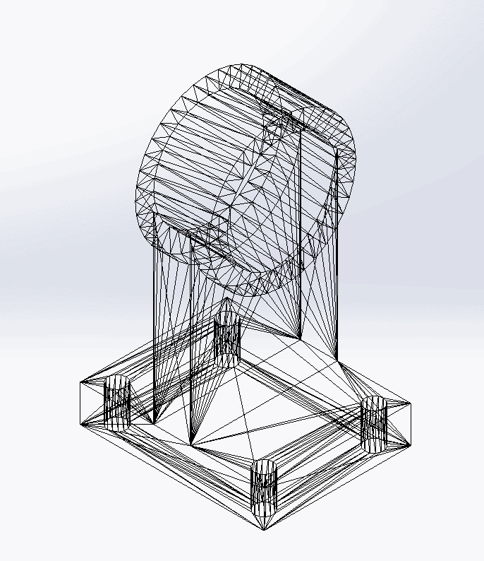
3MF Files that are imported as graphics bodies will now retain appearances and textures that were added using 3rd party CAD software.
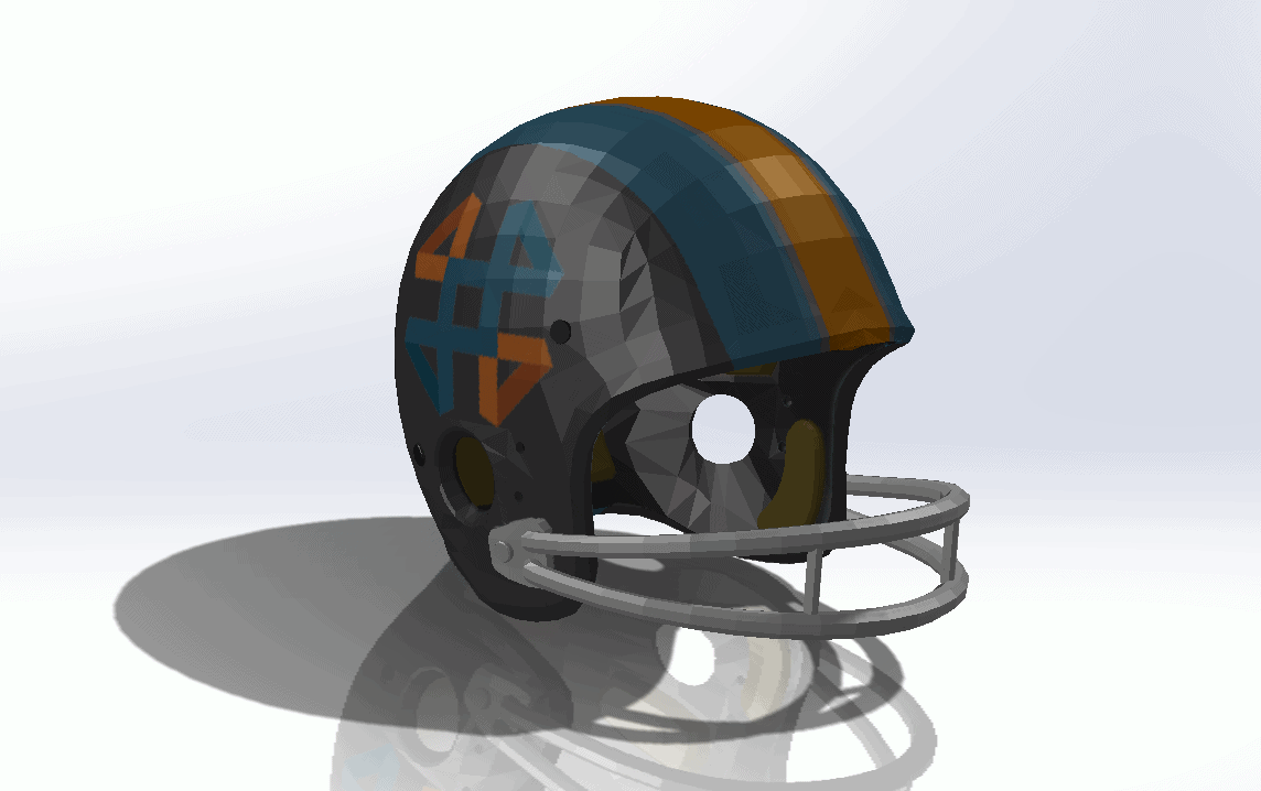
The new options for graphics body visualization in SOLIDWORKS 2018 offer more flexibility and simplicity when working with mesh files.
Surface From Mesh
SOLIDWORKS 2018 introduces a new tool that lets users leverage mesh objects to build surface models. The Surface From Mesh command allows you to create basic analytical surfaces from imported mesh geometry.

To use Surface From Mesh, import a mesh file as a graphics body. When the graphics body is imported, click Insert > Surface > Surface From Mesh. In the Surface From Mesh PropertyManager, choose what geometrical surface type (planar, cylindrical, spherical or conical) you are trying to fit to the mesh geometry.

In this case, we are going to fit a cylindrical surface to the outer cylindrical face.
In the graphics area, select the facets on the model that make up a portion of the desired shape. You can toggle on the paintbrush to “paint” a selection of facets.

I used the paintbrush to select facets around the cylindrical boss.
The Facet tolerance slider allows you to control how many facets you want to include in the surface creation process. A tighter tolerance will make SOLIDWORKS exclude outlier facets and more strictly adhere to the geometrical surface type (plane, cylinder, etc.) you selected. Extend surface size allows you to push the ends of the surface past the ends of the facets to facilitate easier trimming and knitting.
Once you have set the tolerance and Extend surface size, click calculate. A preview of the surface appears.

I slightly tightened the tolerance and used an Extend surface size of 5mm.
Clicking the check mark accepts the new surface. The Surface From Mesh command stays pinned, so that you can continue to add surfaces if you need.

Notice the new surface that is added to the Surface Bodies folder.
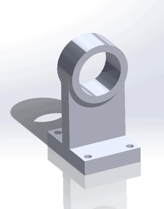
After repeating this process a few times, and with a little bit of trimming/knitting, you now have a solid body!
I hope this part of the What’s New series gives you a better understanding of the new features and functions of SOLIDWORKS 2018. Please check back to the CATI Blog as the CATI Application Engineers will continue to break down many of the new items in SOLIDWORKS 2018. All of these articles will be stored in the category of “SOLIDWORKS What’s New.” You can also learn more about SOLIDWORKS 2018 by clicking on the image below to register for one of CATI’s Design Innovation Summits.
Aarya
Application Engineer
CATI

 Blog
Blog 