How SOLIDWORKS Electrical 2017 Simplifies Collaboration
Teamwork is tried and true regardless of the industry you work in. In product development, the relationship between electrical engineers and mechanical engineers is highly dependent on how well they can collaborate on a project. Having the right tools to work effectively and efficiently not only controls the quality of product designs but the production time frame as well.
SOLIDWORKS Electrical is one such powerful tool for engineers. It not only displays a design to the very last detail but also makes communication extremely easier on both the mechanical and electrical ends of the project.

An electrical engineer generally starts off with a single line schematic, a basic layout of where wires, cables, and components need to be placed before the beginning of production. In the past, this schematic was drawn out manually and information was penciled in to be viewed by all those involved. With SOLIDWORKS Electrical, that tedious and time-consuming process is no longer necessary.
SOLIDWORKS Electrical is a collaborative tool that helps users build their electrical design in a much faster and easier way. It offers a wide variety of symbols and tools that can be used in the design process so nothing gets overlooked. This technical blueprint gives the mechanical engineer a detailed list of the electrical components required and helps identify problems that could occur when creating the mechanical aspects of their design.
A notable key feature in SOLIDWORKS Electrical is the easily searchable library of manufacturer parts that is continuously updated to allow users to chose a certain component. Whether it’s a motor or contactor you’re after, the specific electrical component can be added directly within the software. In SOLIDWORKS Electrical 2017, schematics can now be created from Microsoft Excel spreadsheets or other output files eliminating the need to write it up in the schematic editor.
Once a designer is ready to create a multi-line schematic drawing, SOLIDWORKS Electrical has already made that process easier. Users no longer have to spend extra time re-creating a design they’ve made in the past. SOLIDWORKS Electrical lets users reuse or copy existing designs, which can be dragged into place. Manufacturer parts and cross-references are automatically updated to reflect the current project, and information that was copied can be updated or changed if the user chooses not to use the existing information.
SOLIDWORKS corporation appreciates customer feedback and has solved an issue that many users have asked for. You can now mark wires with the same value as input/output addresses connected. With the latest release, users can now promote the input/output address of the PLC channel to the wire or component mark automatically, saving time and also reducing the risk of error.
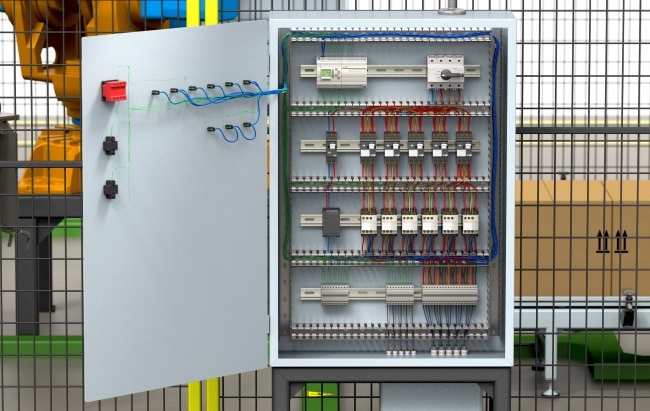
Once the electrical systems have been put in place, mechanical engineers can use SOLIDWORKS Electrical 3D to easily view the design in a different dimension. Since the files are kept in real-time, it’s just a matter of putting the electrical designs into place. In the folder sidebar, users are able to view which components still need to be inserted, and can smoothly be placed where necessary. The electrical schematic can also be viewed in the design with proper color coordinated wires and components giving it a realistic feel.
SOLIDWORKS Electrical doesn’t fail to impress by continuing to speed production, decrease error, and enhance the user experience. With additional tools such as PCB, Circuitworks, and Schematic Standard and Professional, your electrical designs will be ready to go in no time with SOLIDWORKS Electrical 2017. Receive additional information from our webcast: Start to Finish with SOLIDWORKS Electrical.
Related Articles:

 Blog
Blog