EMS for SOLIDWORKS
Bearing
Bearings are devices which constrains the relative motion of a moving (rotating or translating) part. They also aid in reducing friction. When we think of a bearing we often think of only a mechanical bearing (see image) as it is the most commonly used type of bearing.
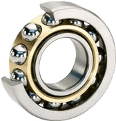
Bearings have numerous applications in the field of machine design, automotive, transportation, oil & gas, medical apparatus etc. They are ubiquitous in any device that has motion. In this brief note, I will discuss a bit about a different kind of bearing, Magnetic bearing and highlight its advantages when compared to a mechanical one.
Limitations of mechanical bearings
Mechanical bearings have limited life due to wear and tear and they require lubrication. In many high speed applications they also may need special type of cooling. Nevertheless it is an exhaustible component that needs to be replaced several times during the life of its parent device.
Magnetic bearing
A magnetic bearing facilitates the same functions of a mechanical bearing by employing a magnetic array of permanent magnets. In short there are 2 sets of concentric magnetic arrays which are held in place by the magnetic forces. Since there is no contact there is no wear and tear and technically the magnetic bearing has a very long life. In addition it can handle very high speeds and large loads with zero friction. This makes a magnetic bearing an excellent choice for machine design, marine, automotive, aerospace and medical devices industry. Recently, there has been a surge in the use of magnetic bearings across various industries. Below is an image of an axial magnetic bearing designed in SoldiWorks. In this design the outer bearing is stationary and the inner bearing is connected to a shaft and is spinning. The weight of the shaft is supported by the magnetic force exerted on the inner bearing.
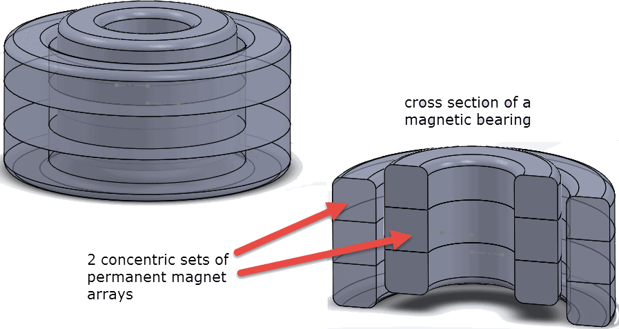
A magnetic bearing design simulated using EMS for SolidWorks
EMS for SOLIDWORKS helps bearing designers to size their magnetic arrays to support various designs of the shaft (basically different weights). This way the bearing can ensure optimum performance. Another advantage of a magnetic bearing is that it can support offset of the inner cylindrical array wrt to the stationary outer cylinder.

EMS software can predict accurately the forces acting on the inner bearing for various offset positions.
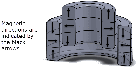
The magnetic arrangement is assembled according to the figure given below. The N-S directions of each magnet is indicated by the black arrows. This type of arrangement can be easily created in EMS and the magnetic flux distribution and the axial force acting on the inner array can be visualized and computed respectively.
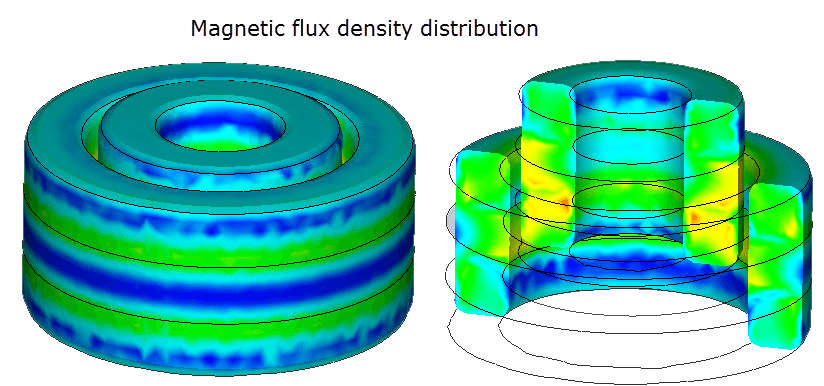
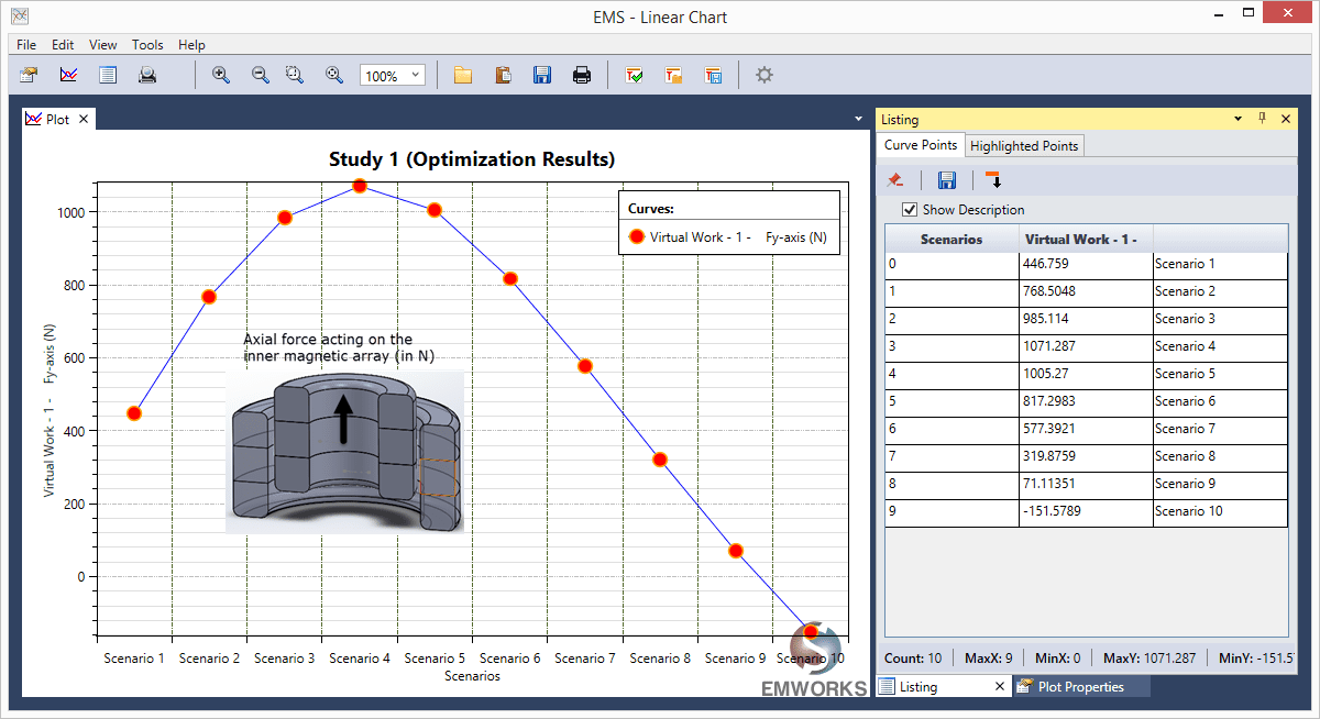
Variation of axial force acting on the inner magnet array with the offset is shown below and is automatically computed by EMS. Note that as the offset increases, so does the axial force but after a point the force reduces. Beyond an offset of 18 mm, the force reverses direction and pulls back the inner array. Using these values of axial force, we can compute the axial magnetic stiffness coefficient
EMS for SolidWorks
EMS for SOLIDWORKS is the first and only completely embedded Gold Certified software for SOLIDWORKS which helps SOLIDWORKS users study their magnetic, electric and electromagnetic designs seamlessly. It can utilize the geometry created using SOLIDWORKS directly for simulation. Its user interface emulates the SOLIDWORKS and hence there is no learning curve associated with the EMS software for SOLIDWORKS users.
Contact us for more EMS information including datasheets, pricing, and more.

 Blog
Blog